Do you have a question about the Eriez 1230 and is the answer not in the manual?
Details the warranty coverage, limitations, and service procedures for Eriez metal detectors.
Explains the availability of field engineers for installation support, system activation, and training.
Offers contact information for technical expertise and application support for metal detectors.
Explains the function, technology, and operational principle of the Metal Detector Model 1230.
Covers intended use, safety signs, dangers of non-compliance, and safety guidelines for operators.
Details the physical dimensions and enclosure ratings (e.g., NEMA) for the control unit.
Lists key technical specifications including housing, weight, ambient temp, voltage, fuse, and inputs/outputs.
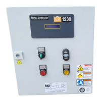
Identifies and describes the components visible on the front panel of the electronic control unit.
Illustrates the main electronic board with labeled connectors (ST1-ST11) and components.
Lists and describes the function of various connectors and terminals on the electronics board.
Identifies indicator lamps (LD1-LD5) and test points on the electronics board.
Details the test points and jumper configurations on the signal analyzer board.
Describes the receiver coil, transmitter coil, and mounting frame assembly.
Details the mounting frame design and specifications for interconnecting cables.
Explains the function, size, weight, and installation of the clip detector.
Describes the application and placement of dual clip detectors for specific conveyor types.
Details the spray marking system for pinpointing metal locations.
Describes the flag drop marker device for pinpointing metal locations.
Lists components of the idler isolation kit used to reduce interference.
Explains the process and conditions for synchronizing multiple metal detectors.
Lists required tools and outlines the unpacking and inspection process for the detector system.
Provides guidelines for choosing the best location and preparing the site for detector installation.
Details the process of isolating idler rollers to break eddy current loops.
Step-by-step instructions for assembling and mounting the search coil assembly components.
Instructions on selecting a location and securely mounting the main control enclosure.
Explains the purpose and installation of the optional swing-away cutout switch.
Details the correct placement and wiring of a single clip detector for optimal performance.
Provides installation and wiring guidance for dual clip detectors.
Details the installation and wiring procedures for the spray marking device.
Lists specifications and provides instructions for mounting the flag drop marker.
Outlines the steps for powering up the system and interpreting start-up indicators and messages.
Explains basic operation using control keys and describes the different operating display screens.
Guides the user through calibrating the detector's sensitivity using test metal samples.
Describes the automatic procedure for calibrating clip time and sensitivity.
Explains the manual method for fine-tuning clip time and sensitivity.
Details how to configure direct and timed output settings, including reset modes and timing.
Explains how to calibrate spray markers and flag drop markers for accurate product identification.
Illustrates the menu structure for Operator Level 1, showing navigation paths.
Details settings like Metal Counter, Total Metal Counter, Device Information, and Logbook.
Displays the menu hierarchy for Operator Level 2, including access to settings.
Explains how to adjust settings like Sensitivity, Reject Duration, and Reject Delay Time.
Covers configuration of Timed Out and Direct Out outputs, and accessing setup menus.
Shows the menu tree for Operator Level 3, including conveying speed and date/time settings.
Details settings for clip mode, duration, sensitivity, and display time.
Explains the clip learning process, received values display, and re-learning options.
Covers password settings, language selection, metal counter reset, and display adjustments.
Lists error messages related to transmitter monitoring and their possible causes and actions.
Details error messages for receiver connection issues and their troubleshooting steps.
Covers error messages related to positive and negative operating voltage faults.
Explains the error message for the swing-away sensor and its resolution.
Lists errors for incorrect signal analyzer setup or clip sensor faults.
Addresses issues with switching outputs activating unexpectedly and possible causes.
Provides the main wiring diagram and details for connecting input power to the detector.
Explains receiver and transmitter antenna connections and cable preparation procedures.
Details wiring for direct output, timed output, and fault output signals.
Covers wiring for clip detectors, spray markers, flag markers, alarms, and other accessories.
Guides on how to prepare the receiver cable, including stripping and grounding shield.
Details the process for preparing the transmitter cable, including stripping and grounding shield.
Explains the terminal connections for the direct output relay and its function.
Describes the terminal connections for the programmable timed output relay.
Details the terminal connections for the fault output relay and its behavior.
Shows the wiring connections for a single clip detector to the control unit.
Illustrates the wiring connections for upstream and downstream clip detectors.
Details the terminal connections for the 24VDC spray marker.
Shows the screw terminal connections for the flag drop marker.
Details terminal connections for panel-mounted 24VDC alarm lights or horns.
Explains wiring for 24VDC pole-mounted alarm lights or horns.
Details wiring for remote-mounted 115/220VAC alarm horns or lights.
Lists the terminal assignments for the voltage regulator connections.
Shows the wiring connections for the swing-away switch (high pile detector).
Details the terminal connections for the remote reset function.
Explains the wiring diagram for synchronizing two or more metal detectors.
Provides contact information and procedures for obtaining service, parts, and repairs for the metal detector.
Identifies the three main electronic boards in the control unit: Evaluation, Signal Analyzer, and Display.
Describes how to transfer the memory module to a new Evaluation Electronics board.
Step-by-step instructions for replacing the main electronics module.
Instructions for removing and installing the display board.
Provides a diagram and list of available spare parts for the metal detector.
Illustrates the components and provides a diagram for the metal detector frame assembly.
| Brand | Eriez |
|---|---|
| Model | 1230 |
| Category | Metal Detector |
| Language | English |