20
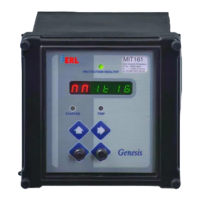
Table 2 shows theoretical value of each characteristic with time multiplier set to 1.000.
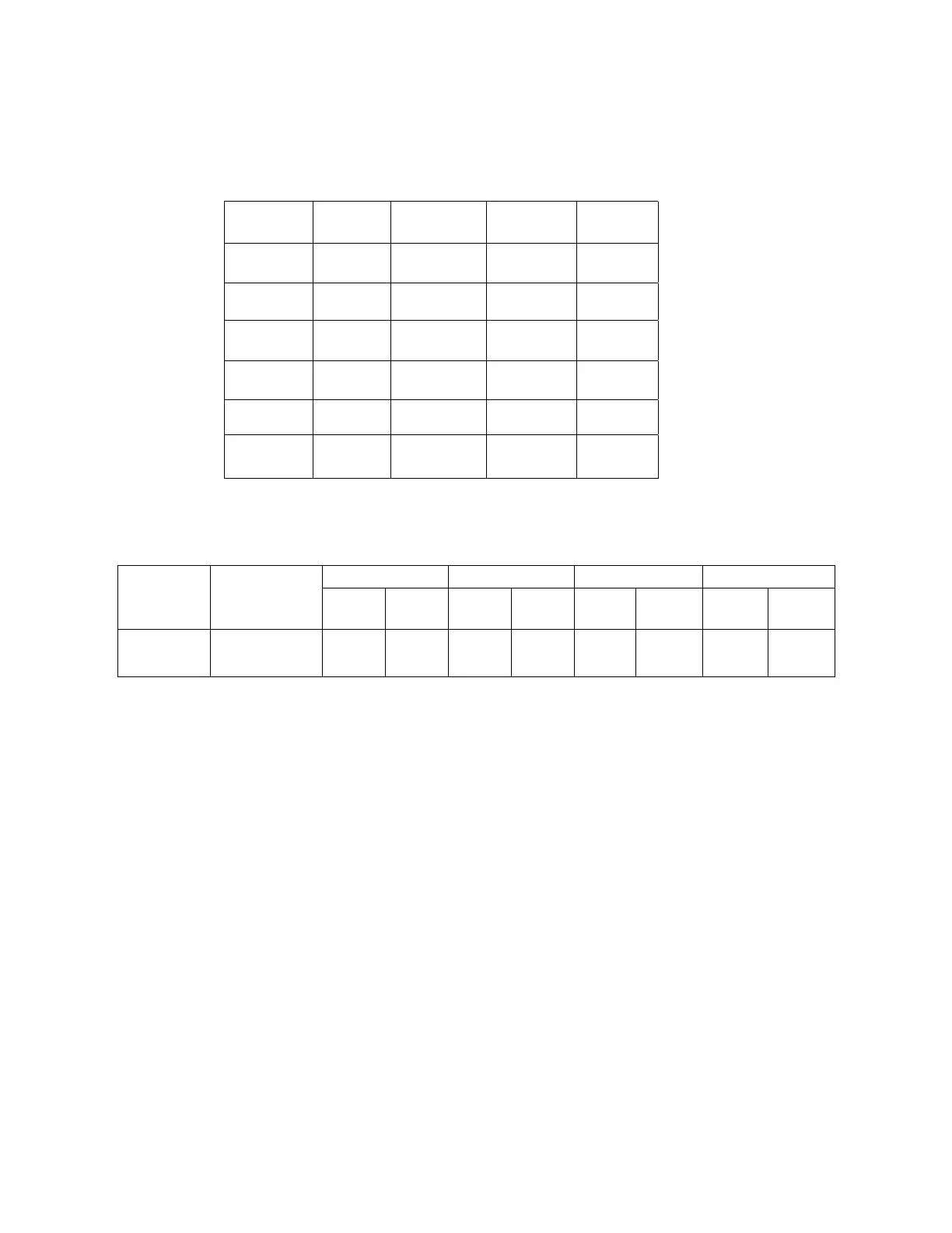
Record the actual results in Table 3 and check that the measured times are within ± 5% or
± 30-m.secs.of theoretical value.
CURVE 2 x Is 5 x Is 10 x Is 20 x Is
SI 3 10.03 4.28 2.97 2.27
SI 1 4.39 1.87 1.3 1.0
EI 26.67 3.33 0.81 0.20
VI 13.50 3.38 1.50 0.71
LTI 120.00 30.0 13.33 6.32
DTL * * * *
TABLE 2 * USER SETTING
2 x Is 5 x Is 10 x Is 20 x Is
Pole Characteristic
(SI3,SI1,EI,
VI LTI,DTL)
Delay Error
(
±
5%)
Delay Error
(
±
5%)
Delay Error
(
±
5%)
Delay Error
(
±
5%)
LOWSET
TABLE 3
5.2.3. O
UTPUT CONTACTS COMBINATION
a) Starter - C/O
This contact is to be used while testing the pick up and reset value of the relay.
b) Common Trip & Alarm for E/F and LOW SET – 2 N/O contacts
These contacts to be used while testing the E/F & LOWSET characteristics.
c) E/F – 1 N/O contact
This contact to be used while testing the E/F characteristic.