Do you have a question about the ESA VT585WB and is the answer not in the manual?
Ensures equipment protection by preventing malfunction due to communication faults with the host controller.
Follow wiring and grounding recommendations to prevent device damage or electrical shock.
Provides guidelines on proper use, avoiding damage from liquids, dust, sunlight, jolting, or chemicals.
A device for controlling or monitoring productive processes, sending commands, and displaying information.
Remember to lay measurement, monitoring and communication cables apart from power cables.
It is essential to use suitably shielded cables for communication signal connections.
Details specifications of disturbance suppression filter circuits.
Details the pin configuration for the 4-pin power supply connector.
Specifies conductor cross-sections, wire length, and screw grip pressure for power supply.
Illustrates connections that must not be made to prevent VT damage.
Provides a wiring scheme to avoid damaging the VT.
Explains how to adjust display contrast by changing a value.
Applies to CAN series; explains activating termination resistances via a jumper.
Explains MAC address identification for Ethernet series terminals and its programming.
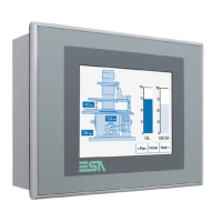
Lists technical characteristics of the VT595W, including display, touch screen, and keyboard.
Lists all functions and objects realizable with the VT in alphabetical order.
Explains the necessary files (firmware, driver, project) for initial VT loading.
Details steps for preparing the VT to receive data transfer using VTWIN software.
Provides information about loaded project, driver name, version, network address, and last error.
Shows front/back views and sequence for mounting VT using nuts.
Provides advice on respecting screwing sequence and initial/final tightening.
Discusses serial communication susceptibility to disturbances and recommends shielded cables.
Details necessary pin jump-connections for communication ports to function properly.
Describes the MSP connector (D-Sub 25 pin female) and its communication capabilities (RS232, RS422, RS485).
Describes the ASP connector (D-Sub 15 pin female) and its communication capabilities (RS232, RS485).
Describes the ASP-15L connector (D-Sub 15 pin female) and its communication capabilities (RS232, RS485).
Describes the ASP-9 serial port (D-Sub 9 pin male) and its RS232 communication.
Describes the ASP-8 serial port (Minidin 8 pin female) and its RS232 communication.
Explains PC connection for project transfer using a female 25-pole connector.
Details connections for CAN series, including termination resistances.
Explains the calibration procedure for the resistive touch screen.
Explains the driver that enables communication with any intelligent device not supported by standard drivers.
Details how to change VT address, baud rate, and parameters using specific key presses.
Details how to change VT address, baud rate, and parameters using specific key presses.
Details how to change VT address, baud rate, and parameters using specific key presses.
Explains the essential steps for correctly shielding interface cables.
| Touchscreen | Yes |
|---|---|
| Touch Technology | Resistive |
| Ethernet | 10/100 Mbps |
| USB Ports | 1 x USB 2.0 |
| Protection Rating | IP65 |
| Communication Interfaces | Ethernet, RS-232/422/485, USB |