EasyManua.ls Logo

ESAB Heliarc 250 - User Manual

ESAB Heliarc 250
24 pages
Print Icon
To Next Page IconTo Next Page
Loading...
F-15-047-A
February, 1995
Heliarc
®
250 AC/DC
SQUARE WAVE POWER SOURCES
NOTE: This manual is also suitable for use with L-TEC Heliarc 250 HF plus.
These INSTRUCTIONS are for experienced operators. If you are not fully familiar with the principles of operation and
safe practices for arc welding equipment, we urge you to read our booklet, "Precautions and Safe Practices for Arc
Welding, Cutting, and Gouging", Form 52-529. Do NOT permit untrained persons to install, operate, or maintain this
equipment. Do NOT attempt to install or operate this equipment until you have read and fully understand these
instructions. If you do not fully understand these instructions, contact your supplier for further information. Be sure
to read the Safety Precautions (Section 1) before installing or operating this equipment.
Be sure this information reaches the operator.
You can get extra copies through your supplier.
INSTRUCTION MANUAL
P/N 31310 - Heliarc 250 AC/DC w/power factor
P/N 31300 - Heliarc 250 AC/DC w/o power factor
Question and Answer IconNeed help?

Do you have a question about the ESAB Heliarc 250 and is the answer not in the manual?

Summary

USER RESPONSIBILITY

SAFETY PRECAUTIONS

Protect Yourself and Others

Safety measures for personal protection from arc rays, heat, and noise.

Fires and Explosions

Precautions to prevent fires and explosions caused by welding operations.

Electrical Shock Hazards

Warnings and procedures to avoid electrical shock during operation.

Electric and Magnetic Fields

Information on potential EMF exposure and mitigation for welders.

Fumes and Gases

Precautions regarding hazardous fumes and gases generated during welding.

Cylinder Handling

Safe procedures for handling compressed gas cylinders to prevent rupture.

Equipment Maintenance Safety

Safety guidelines for performing maintenance on welding equipment.

Additional Safety Information

References to further publications for safe welding practices.

DESCRIPTION

Introduction

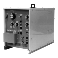
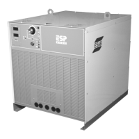
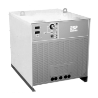
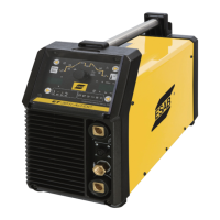
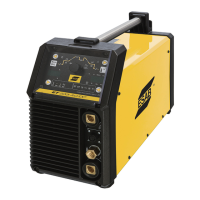
Overview of the Heliarc 250 AC/DC welding power source capabilities.

Duty Cycle

Explanation of duty cycle and how it affects machine operation and output.

INSTALLATION

Unpacking and Placement

Instructions for safely unpacking and positioning the welding power source.

Primary Electrical Connections

Guidelines for connecting the unit to the primary power supply.

Input Terminal Board Connections

Details on connecting input voltage and ground to the terminal board.

External Primary;Secondary Connections

Procedures for connecting external primary and secondary electrical circuits.

Accessories

Information on available optional accessories for the welding unit.

Optional Accessories

Details on optional accessories like water coolers and remote controls.

OPERATION

Control Functions Overview

Explanation of various control switches and potentiometers on the unit.

Sequence of Operation

Step-by-step guide for operating the welding machine.

Stick Welding Procedure

Detailed steps for performing Stick welding with the unit.

TIG Welding Procedure

Detailed steps for performing TIG welding with the unit.

MAINTENANCE

General Maintenance and Cleaning

Basic maintenance tasks, safety, and procedures for cleaning the unit.

Component Servicing

Guidelines for lubricating fan motors and servicing spark gaps.

Component Testing and Replacement

Procedures for testing and replacing bridge assembly components.

TROUBLESHOOTING

General Troubleshooting

General advice and precautions for troubleshooting the welding unit.

Troubleshooting Guide

A guide to diagnose and resolve common operational problems.

REPLACEMENT PARTS

General Parts Ordering

Guidelines for ordering replacement parts, including necessary information.

Front View Parts

Illustration and part numbers for components on the front panel.

Right Side View Parts

Illustration and part numbers for components on the right side.

Left Side View Parts

Illustration and part numbers for components on the left side.

COMMUNICATION GUIDE - CUSTOMER SERVICES

Overview

The Heliarc® 250 AC/DC is a constant current AC/DC welding power source designed for high-quality TIG and Stick welding in both AC and DC modes. It is available in two models: P/N 31310 (with power factor correction) and P/N 31300 (without power factor correction). This manual is also suitable for use with the L-TEC Heliarc 250 HF plus.

Function Description:

The device utilizes unique magnetic and solid-state circuits to provide excellent arc conditions for TIG welding and high-alloy stick electrodes. Its non-saturating current limiting reactor and electronic feedback control prevent high current surges, reducing spatter on stick electrodes and tungsten spitting during TIG welding. An electronic firing circuit with voltage compensation ensures stable operation despite line voltage variations of +/-10 percent. The unit offers a wide range of volt-ampere curve characteristics, making it a versatile constant current AC/DC power source.

Important Technical Specifications:

  • Rated Output @ 40% Duty Cycle: 250 Amps @ 30 Volts AC/DC, TIG/Stick.
  • Open Circuit Voltage: 79 Volts AC / 72 Volts DC.
  • Output Current Range:
    • Low Range: 5 to 60 Amps.
    • High Range: 15 to 320 Amps (20 to 320 Amps*).
  • Input Voltage AC: 208/230/460 V, 1P, 60 Hz.
  • Input Current @ Rated Load in Amperes (without P.F.C.):
    • 208 V: 107 A
    • 230 V: 96 A
    • 460 V: 48 A
  • Input Current @ Rated Load in Amperes (with P.F.C.):
    • 208 V: 83 A
    • 230 V: 74 A
    • 460 V: 37 A
  • Power Factor @ Rated Load:
    • Without P.F.C.: Approx. 52%
    • With P.F.C.: Approx. 76%
  • Auxiliary Power Output: 115 V AC, 15 Amp, 60 Hz.
  • Dimensions:
    • Width: 16 in. (406 mm)
    • Depth: 30 in. (762 mm)
    • Height: 22 in. (559 mm)
  • Weight: 380 lbs (171 kg) for P/N 31310; (295 lbs, 179 kg*) for P/N 31300.
  • Duty Cycle: Rated at 40% duty cycle (250 amps for 4 minutes, off for 6 minutes in a 10-minute period). Duty cycle can be increased with decreased welding current and vice versa. Note that the duty cycle of the unit without P.F.C. is approximately 50% less (25% less on unit with P.F.C.) when Balance Control is in the "max. penetration" position.

Usage Features:

  • Power On-Off Switch (ROS): Controls power to the fan motor, main transformer, and control circuitry. Input voltage remains present at the terminal board and switch unless the customer's line switch is off.
  • TIG-Stick Mode Switch (TSS): Selects between STICK mode (contactor circuits energized, continuous welding power) and TIG mode (contactor and TIG sequencing circuits controlled by a remote device like a foot or torch switch).
  • Current Control (Panel-Remote) Switch (PRS): Determines whether welding current is controlled from the power source's Weld Current potentiometer (PANEL) or from an optional remote foot or hand control (REMOTE). In REMOTE mode, the remote control varies current within the range preset on the panel potentiometer.
  • Remote Torch (Contactor Receptacle - RTR): Low-voltage receptacle for connecting remote foot control or torch switch accessories to control the TIG welding output power.
  • Remote Control Receptacle (RCC): Allows plugging in remote accessories for current and/or contactor control.
  • Current Selector Switch (CSS): A 3-position switch for selecting AC, DCSP (work positive, torch/electrode negative), or DCRP (work negative, torch/electrode positive) output current. AC is primarily for aluminum and magnesium, DCSP for steel, copper, and refractory metals, and DCRP for thin sheets of metal. This switch should not be changed while welding or under load.
  • Current Range Selector Switch (SW1): A 2-position switch (on the SCR Control PC Board) for coarse selection of output current ranges (low 5-60 Amps, high 15-320 Amps). Not to be changed while welding or under load.
  • Current Control Potentiometer (CCP): Fine adjustment of welding current within the selected range.
  • High Frequency (Solenoid) Selector Switch (HFS): A 3-position toggle switch (on the Logic PC Board) controlling high frequency and shielding gas. Positions include Off (no HF, gas solenoid de-energized, for stick welding), Continuous (HF and gas throughout welding cycle, for AC TIG), and Start (HF initiates and cuts off after arc establishment, gas remains on, for DC TIG).
  • Post Flow Control (PFP): Potentiometer (on the Logic PC Board) for timed post-flow of shielding gas (5 to 45 seconds) after the arc breaks.
  • Auxiliary 115-Volt Receptacle (J3): Duplex receptacle for 115-volt power, protected by a 15-amp circuit breaker.
  • Arc Force Potentiometer (AFP): Used in STICK mode only to adjust short circuit current and arc stability. Lower settings provide a softer arc, higher settings a more forceful, penetrating arc.
  • Balance Control Potentiometer (BP): Changes wave balance for TIG welding (not operative in Stick welding). "Max. Cleaning" (counterclockwise) provides balanced wave (50/50 reverse and straight polarity) for maximum cleaning and minimum penetration. Turning clockwise towards "Max. Penetration" lessens cleaning and increases penetration. This "unbalanced" wave output is for AC TIG only. When using "Maximum Penetration" in AC TIG, duty cycle is reduced by 50% (25% with P.F.C.), and input current increases by approximately 40%. For DC TIG, Balance Control should always be set to "Maximum Cleaning."

Maintenance Features:

  • Cleaning: Since there are no moving parts other than the fan, maintenance primarily involves keeping the interior of the cabinet clean. Periodically remove the cover and blow accumulated dust and dirt from air passages and internal components using low-pressure air. This ensures adequate cooling, especially for rectifier bridge plates and PC boards. The frequency of cleaning depends on the unit's location and atmospheric dust levels.
  • Lubrication: Fan motors with old tubes require lubrication after one year. Motors without oil tubes are permanently lubricated.
  • Spark Gap Servicing: This component of the high-frequency assembly may require readjustment after extended operation or if erratic high-frequency operation occurs. Gaps should be adjusted with a feeler gauge (factory-set at 0.025 inches +/- 0.002 inches). Cleaning and dressing of spark gap points are not recommended; points (P/N 673578) should be replaced as a set. High-frequency radiation increases as the gap increases, potentially causing interference with other electronic equipment.
  • Testing and Replacing Bridge Assembly Components:
    • Silicon Diode Rectifier (D1-D2): Disconnect the power lead and check resistance in forward and reverse directions with an ohmmeter (R x 1 scale). A good diode reads high in reverse and low in forward. When replacing, ensure mounting surfaces are clean, coat with Dow-Corning No. 340 silicon heat sink compound, and torque nuts to 275-325 inch-lbs max.
    • Silicon Controlled Rectifier (SCR): Disconnect SCR wiring (but do not unclamp) and check resistance in both directions with an ohmmeter (R x 1 scale). A good SCR reads high in both directions. If low or zero, the SCR is defective. To check the gate, connect the gate lead to the anode and read forward resistance across anode to cathode. When replacing, ensure mounting surfaces are clean, coat with Alcoa No. 2 electrical joint compound, and ensure correct polarity. Place the top clamp piece over bolts, tighten nuts hard finger tight, ensuring the clamp piece is parallel to the top plate. Then tighten each nut approximately 1/4 turn at a time for two complete revolutions until the force indicator on the clamp assembly reads 1.0 kilopounds (1000 lbs).

ESAB Heliarc 250 Specifications

General IconGeneral
BrandESAB
ModelHeliarc 250
CategoryPortable Generator
LanguageEnglish

Related product manuals