24
SECTION 3 INSTALLATION
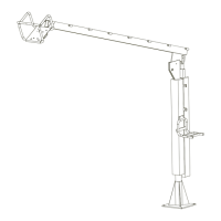
3.5 INSTALLATION OF THE GAS HOSE
Route the appropriately sized gas hose through the boom arm and connect one end
to the wire drive / drive box assembly and the other end to the gas supply. Tighten
connections completely to ensure a good gas connection.
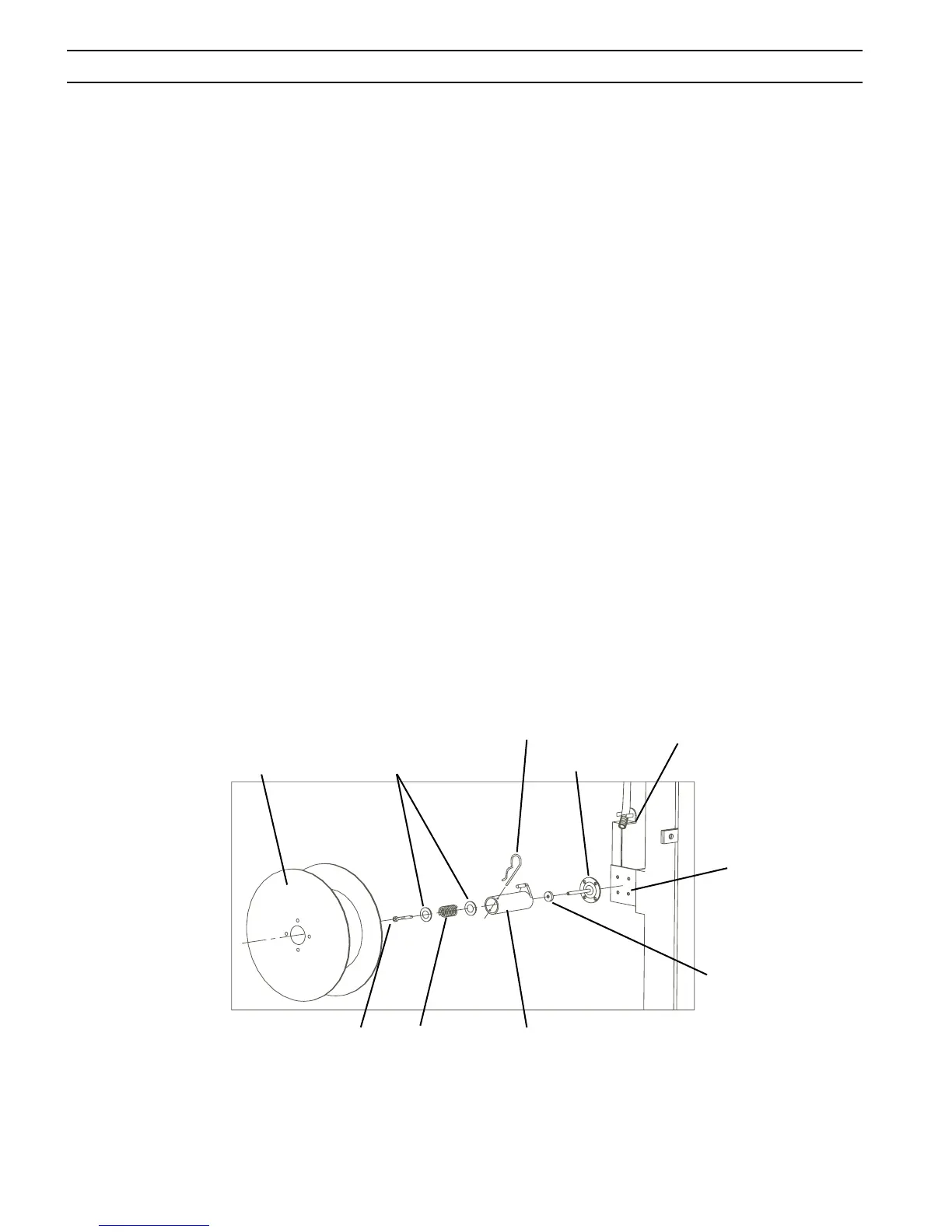
Conduit Bushing Bracket
2" Spindle Assembly (P/N 948259)
Roll Pin
Spindle Washers
Hitchpin
Braking Pad
Bolt
Wire Spool
Spring
Wire Spool Bracket
3.6 INSTALLATION OF THE ELECTRODE CONDUIT
Route conduit and protective cover through side rings of the boom arm to line up
with wire feeder inlet guide.
3.7 INSTALLATION OF THE 2" SPINDLE ASSEMBLY (P/N 948259)
Install the 2" spindle assembly using the (4) 5/16 dia. bolts, washers and nuts. Place the
larger washer into the spindle assembly before installation to the boom mast spindle
bracket. Line up the small hole on the spindle assembly with the roll pin on the mast.
After the 2" spindle assembly is in place, completely tighten the bolt.
3.4 INSTALLATION OF THE CONTROL CABLE ASSEMBLY (SHD
only)
Install the Control Cable Assembly between the wire drive / drive box assembly and
the control box assembly. The pin end of the Control Cable Assembly connects to
the control box assembly. The socket end of the Control Cable Assembly connects
to the wire drive / drive box assembly. Route the cable through the boom arm and
attach to the control box. Tighten all connections completely to ensure a good
electrical connection.