Do you have a question about the EsiWelma Sensigas URD20SE and is the answer not in the manual?
Describes where and why the detectors are used in industrial environments.
Explains how the detector functions during gas leakage and compares concentration values.
Provides the part number for ordering the detector and contact for special versions.
Crucial safety advice regarding cover tightening and operational warnings.
Details on wiring terminals, jumper circuits, and connectors for setup.
Guidance on cable selection and 4-20mA output reference settings.
Configuration of 4-20mA signal operating mode and alarm threshold values.
Selecting contact types (NC/NO) and configuring relay operating mode.
Verifying sensor status, output, and LEDs after installation.
Procedures for sensor testing, calibration, and safe decommissioning.
Information on product warranty, accessories, and dimensions/weight.
Explanation of EC directives, ATEX markings, and certifications.
Fields for recording installation site, product order, and routine checks.
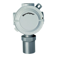
The EsiWelma URD20SE is a Sensigas® gas detector designed for the detection of carbon dioxide (CO2) in industrial environments. It is ATEX II 2G Ex d IIC T6 Gb certified, making it suitable for use in Zone 1 classified areas where explosive gas atmospheres may be present.
The URD20SE utilizes a Nondispersive Infrared (NDIR) sensor to detect CO2 leaks or emissions. It operates on an 11-28Vdc power supply. The detector is capable of providing up to three alarm thresholds, in addition to indicating a sensing element failure. An integrated LED on the sensor body provides visual feedback on the operating status. The device also features an automatic countdown of the sensor's life.
The detector can operate in a stand-alone mode, providing a 4-20mA output signal proportional to the measured CO2 concentration. Alternatively, it can be expanded with an optional voltage-free contact relay card (UZR20.4) that offers four digital outputs: Pre-alarm, 1st alarm threshold, 2nd alarm threshold, and Sensor fail. When a gas leakage is detected, the device compares the measured concentration against predefined threshold setpoints and energizes the associated relays. The 4-20mA output continuously provides information on the measured concentration.
The URD20SE is particularly useful in industrial environments, hospitals, fermentation plants, greenhouses, and stables, or any location where carbon dioxide is stored, generated, or produced.
Sensor Type: NDIR (Nondispersive Infrared) Detectable Gas: Carbon dioxide (CO2) Power Supply: 11-28Vdc Max Power Consumption: 3.2W Measuring Range: 0...20,000 ppm Precision: ± 5% full scale, ± 10% readout Repeatability: ± 5% full scale, ± 10% readout Measurement Resolution: 20 ppm Microprocessor Resolution: 1024 points (10 bit) Digital Filter System: Kalman Filter Watchdog: Internal Warm-up Time: < 2m Stabilization Time: < 2m Response Time (T90): < 25s Average Sensor Life (in air): 255 weeks
4-20mA Output:
Environmental Conditions:
Visual Warnings: Red LED visible on the sensor body Dimensions (HxWxD): 164x100x82mm Weight: 0.8Kg
Optional Relay Card (UZR20.4):
ATEX Markings:
Installation: The URD20SE is designed for installation in Zone 1 classified areas. Due to CO2 being about one and a half times denser than air, it tends to collect at floor level in enclosed, unventilated spaces. Therefore, the sensor should be installed approximately 30 cm above the floor. Specific installation guidelines include:
Cabling:
Configuration: Default settings are provided in the "Technical Specifications." To change settings, power off the device, input new settings via the JP2 jumper circuit or S1 DIP switch, then power up. The 4-20mA output reference polarity can be selected via JP2 jumpers. The operating mode of the 4-20mA signal (proportional or threshold mode) is configured using the 5th selector of the S1 DIP switch. Threshold limit values for the optional relay card or the 4-20mA signal's threshold operating mode can be set using the first four selectors of the S1 DIP switch, with values expressed as a percentage of full scale (e.g., 3, 5, 10% or 10, 20, 40% default). Custom threshold values can be set using the TUS40 handheld terminal when the first four DIP switch selectors are in the OFF position.
Optional Relay Card Installation: The UZR20.4 relay card expands the control card with four SPDT relays for pre-alarm, 1st threshold, 2nd threshold, and sensor fail conditions, along with LED alerts. Installation involves inserting the connection slot into the CN3 connector, ensuring the flexible tab is towards the main terminal board, fitting the card snugly, and pulling the flexible tab towards the main terminal board. Electrical configuration requires selecting the relay operating mode (direct or reverse) and contact type (NC or NO) using JP1-JP4 jumpers and the 6th selector of the S1 DIP switch.
Sensors Lifetime: The average sensor lifetime is based on typical usage in a pollution-free environment. High concentrations of pollutants can shorten the sensing element's life. The detection system must be continuously supplied with energy throughout the sensors' lifetime; seasonal use is not recommended.
Checklist After Installation:
Routine Maintenance: A functional sensor test should be carried out every three to six months, repeating the post-installation checks.
Corrective Maintenance: If abnormalities are found, the sensor should be returned to the supplier/installer for manufacturer repair. Recalibration may be necessary using the TUL40.. gas calibration kit and the TUS40 handheld terminal, connected via the CN4 communication interface. Instructions for recalibration are provided with the handheld terminal.
Decommissioning: To decommission, remove power, disconnect all wiring and conduits, and dismount the housing from any blocking systems.
Warranty: EsiWelma products have a 12-month warranty from the installation date, not exceeding 24 months from the manufacturing date. Proof of installation (data, stamp, and signature on the data sheet) is required for warranty claims. A copy of the warranty data sheet must be sent when returning the product under warranty.
Accessories:
| Brand | EsiWelma |
|---|---|
| Model | Sensigas URD20SE |
| Category | Gas Detectors |
| Language | English |