86 74 52 31
E
D
C
B
A
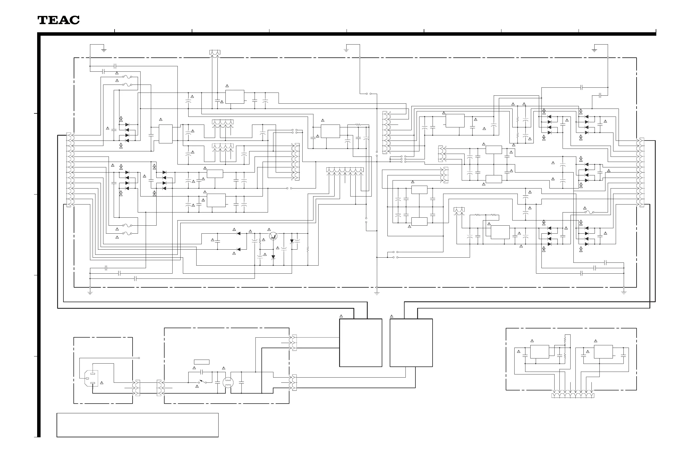
SCHEMATIC DIAGRAM
X-01
POWER PCB, INLET PCB, PSW PCB, REG PCB
SUPER AUDIO CD PLAYER
XX--0011
2 nd Issue; August 2004
INSTRUCTIONS FOR SERVICE PERSONNEL
BEFORE RETURNING APPLIANCE TO THE CUSTOMER, MAKE LEAKAGE-
CURRENT OR RESISTANCE MEASUREMENTS TO DETERMINE THAT EXPOSED
PARTS ARE ACCEPTABLY INSULATED FROM THE SUPPLY CIRCUIT.
NOTES:
1. Resistor values are in ohms (k=kilo-ohms, M=megohms).
2. Capacitor values are in microfarads (p=picofarads).
3. £Parts marked with this sign are safety critical components.
They must always be replaced with identical components-refer
to the appropriate parts list and ensure exact replacement.
 Loading...