Do you have a question about the Esse-ti 4G.VoLTE and is the answer not in the manual?
Provides crucial information on safe installation, use, and maintenance of the product.
Details the process of making the physical installation of the gateway.
Explains the device's capability to make and receive calls over the 4G LTE/UMTS/GSM network.
Details the 4G.VoLTE CAN model with a DB-9 connector for data and email forwarding.
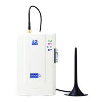
Step-by-step instructions for inserting the SIM card and connecting the antenna.
Guidance on connecting the gateway to the telephone line via RJ-11 or TEL terminal.
Procedures for connecting the gateway to the power supply (230 Vac or 12 Vdc).
Procedure to power on the gateway and verify initial registration.
Instructions for physically mounting the gateway on a wall.
Best practices and advice for installing the gateway.
Table detailing the device's power consumption under various conditions.
Configuration of telephone line voltage and automatic country setting.
Settings for Caller ID (CLIP/CLIR) and roaming services.
Setup for notification numbers and administrator telephone number.
Configuration for SIM card expiration and battery status checks.
Configuration for monitoring external power supply failures.
Configuration of relay notifications for failures and periodic test functions.
Settings for automatically converting dialed telephone numbers.
Configuration of voice call codecs for different network types.
Setting the communication technology and restoring default settings.
Defines the required format for sending programming commands via SMS.
Describes the format of SMS messages sent by the gateway as notifications.
Procedures for answering incoming calls and making outgoing calls.
How to measure the 4G LTE/UMTS/GSM signal strength.
Procedure to check remaining days until SIM card expiration.
Procedure to check the current battery status of the device.
Instructions for activating and deactivating the relay function.
Instructions for configuring the relay to operate in pulse mode.
Procedure to obtain advanced device and radio cell information via SMS.
Configuration for communication standards (RS-232, RS-485, CAN-bus) and parameters.
Procedures for sending and receiving SMS messages through the DB-9 connector.
Instructions for sending emails and configuring the COMNet server connection.
Explains the COMNet system for remote connectivity via serial communication.
Details setting up the COMNet system and the data flow for remote monitoring.
Provides the pinout diagram for the female DB-9 connector.
Describes the meaning of various audible tones and call signals.
Explains the GREEN LED indicating the 4G LTE/UMTS/GSM signal level.
Explains the RED LED indicating the device's operational status.
Explains the WHITE LED indicating line status or data transmission.
Explains the BLUE LED indicating the power supply status.
Lists common detected problems, their root causes, and suggested solutions.
States the equipment's compliance with Directive 2014/53/EU.
| Cellular Technology | 4G LTE |
|---|---|
| VoLTE Support | Yes |
| Ethernet Ports | 1 |
| Display | No |
| Operating System | Proprietary |
| SIM Type | Mini-SIM |