12-9 Replacement of the switching power supply, PC I/F board ASSY,
the power supply board ASSY
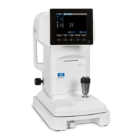
1) Remove the base cover 1. The main unit needs to be tipped sideways. Tip the device on
the buffer such as a sponge as you can see the bottom of the device.
2) Unscrew 4 fixing screws of the base cover 2.
Fixing screws
Base cover 1
Base cover 2
3) Stand the device up and remove the main unit cover L and R (refer to 12-1).
4) Remove the chin rest ASSY (refer to 12-6).
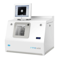
5) Move the fluctuation mechanical unit to the upper end and back and forth mechanical
unit to the edge of the joystick side.
Front cover AS
6) Remove the front cover ASSY (refer to 12-5).
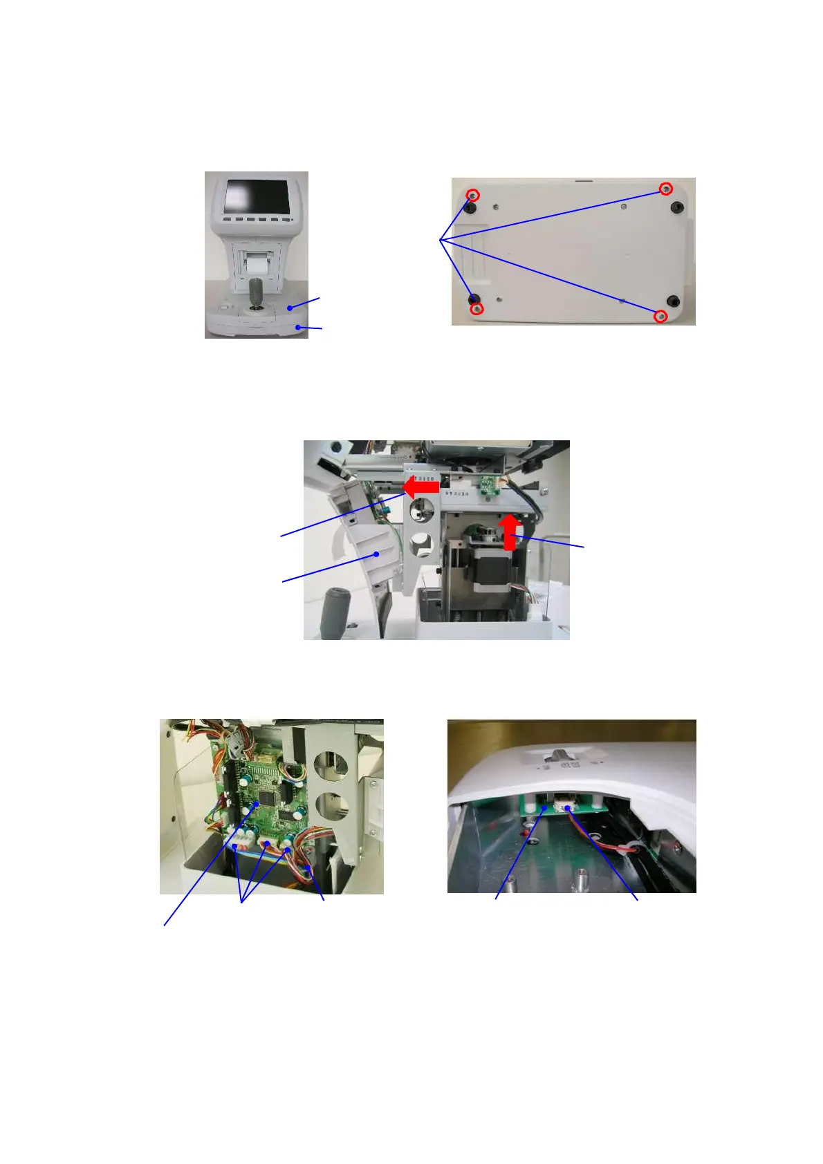
7) Remove 3 harnesses that are connected to 3 axes control board ASSY and cut the tielap at
the lower right side of the board.
3 axes control board ASSY
Chin holder vertical
movement switch board ASSY
Harness
8) Remove the joystick ASSY (refer to 12-7) and remove the harnesses that are connected
to the chin holder vertical movement switch board ASSY.
9) Lift the base cover 1 with protecting it with a sponge etc. not to damage it with the sheet metal.
 Loading...