Do you have a question about the Essilor AKR 750 and is the answer not in the manual?
Overall view of the device's wiring with labeled components.
Details wiring connections for the LCD assembly.
Illustrates wiring for the chin rest assembly.
Depicts wiring diagram of the device's base unit.
Overview of main control boards and their functions.
Steps to resolve the 'RETRY' error message.
Guidance for resolving the 'EEPROM fault' error.
Steps to troubleshoot the 'Motor fault' error.
Instructions on accessing and initiating the maintenance mode.
Details various functions available within maintenance mode.
Outlines the basic procedure for device calibration.
Specific steps for performing REF calibration.
Detailed procedure for KRT calibration.
How to verify and confirm calibration results.
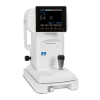
Description of the expected image in normal operation.
Steps to resolve issues when no measurement image appears.
Explains cases of unusable measurement images.
Procedure for replacing main unit covers and the 3-axis control board.
Steps to replace the optical control board ASSY.
Procedure for replacing the optical unit ASSY and CMOS harness.
Steps to replace LCD related parts and boards.
| Category | Medical Equipment |
|---|---|
| Brand | Essilor |
| Model | AKR 750 |
| Function | Edging lenses |
| Operation Mode | Automatic |
| Bevel Types | Multiple bevel types available |