EST INTERNATIONAL
201 CITY CENTRE DRIVE SUITE 500, MISSISSAUGA, ONTARIO, CANADA L5B 2T4
PHONE: (001) 905-2 70-1711 • FAX: (001) 905-270-9553 • WORLD WIDE WEB: WWW.ESTINTERNATIONAL.COM
U.S. SALES: SARASOTA, FL; PHONE 941-739-4638; FAX 941-727-1214 • CANADA SALES: OWEN SOUND, ON; PHONE 519-376-2430; FAX 519-376-7258
INTERNATIONAL
Issue 5Issue 5
Issue 5Issue 5
Issue 5
Literature Sheet #85001-0269Literature Sheet #85001-0269
Literature Sheet #85001-0269Literature Sheet #85001-0269
Literature Sheet #85001-0269
Page 1 of 4Page 1 of 4
Page 1 of 4Page 1 of 4
Page 1 of 4
Not to be used for installation purposes.Not to be used for installation purposes.
Not to be used for installation purposes.Not to be used for installation purposes.
Not to be used for installation purposes.
EDWARDS SYSTEMSTECHNOLOGY
TM
ANALOG ADDRESSABLE INITIATING DEVICES
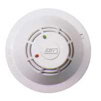
Intelligent Photoelectric
Smoke Detector
Model SIGA-PS
Note: Some features described here may not be supported by all
control systems. Check your control panel’s Installation and
Operation Guide for details.
Features
!!
!!
! Integral microprocessor
!!
!!
! Non-volatile memory
!!
!!
! Automatic mapping device
!!
!!
! Electronic addressing
!!
!!
! Environmental compensation
!!
!!
! Intelligent detector
!!
!!
! Wide 0.67% to 3.77%/ft. sensitivity range
!!
!!
! Twenty pre-alarm sensitivity values, set in 5% increments¹
!!
!!
! Identification of dirty or defective detectors
!!
!!
! Automatic day/night sensitivity adjustment
!!
!!
! Twin RED/GREEN status LEDs
!!
!!
! Standard, relay, fault isolator, and audible mounting bases
!!
!!
! Designed and manufactured to ISO 9001 standards
Description
EST’s Signature Series Model SIGA-PS Intelligent Photoelectric
Smoke Detector gathers analog information from its smoke sensing
element and converts it into digital signals. The detector’s on-
board microprocessor measures and analyzes these signals. It
compares the information to historical readings and time patterns
to make an alarm decision. Digital filters remove signal patterns
that are not typical of fires. Unwanted alarms are virtually elimi-
nated.
The microprocessor in each detector provides four additional benefits
- Self-diagnostics and History Log, Automatic Device Mapping,
Stand-alone Operation and Fast, Stable Communication.
Self-diagnostics and History Log - Each Signature Series detector
constantly runs self-checks to provide important maintenance
information. The results of the self-check are automatically updated
and permanently stored in the detector’s non-volatile memory.
This information is accessible for review any time at the control
panel, PC, or by using the SIGA-PRO Signature Program/Service
Tool.
The information stored in the detector’s memory includes:
- detector type, serial number, and address
- date of manufacture, hours of operation, and last maintenance date²
- current detector sensitivity and environmental compensation
values
- original detector sensitivity values upon manufacturing²
- number of recorded alarms and troubles²
- time and date of last alarm¹
- analog signal patterns just before the last alarm¹
- most recent trouble code logged by the detector — 32 possible
trouble codes may be used to diagnose faults.
In the unlikely event that an unwanted alarm does take place, the
control panel’s history file can be called up to help isolate the
problem and prevent it from happening again.
Automatic Device Mapping - The loop controller learns where
each device’s serial number address is installed relative to other
devices on the circuit. The mapping feature provides supervision
of each device’s installed location to prevent a detector from
being reinstalled (after cleaning etc.) in a different location from
where it was originally. The history log for the detector remains
relevant and intact regardless of its new location.
The Signature Series Data Entry Program also uses the mapping
feature. With interactive menus and graphic support, the wired
circuits between each device can be examined. Layout or “as-built”
drawing information showing wire branches (T-taps), device types
and their address are stored on disk for printing hard copy. This
takes the mystery out of the installation. The preparation of “as-built”
drawings is fast and efficient.
Device mapping allows the Signature loop controller to discover:
- unexpected additional device addresses
- missing device addresses
- changes to the wiring in the circuit.
¹ EST3 V.2 only.
2
Retrievable with SIGA-PRO programming tool.
Application Notes
Available
CHINA
S