2 / 2 P/N 387047P-EN • REV 06 • ISS 11DEC14
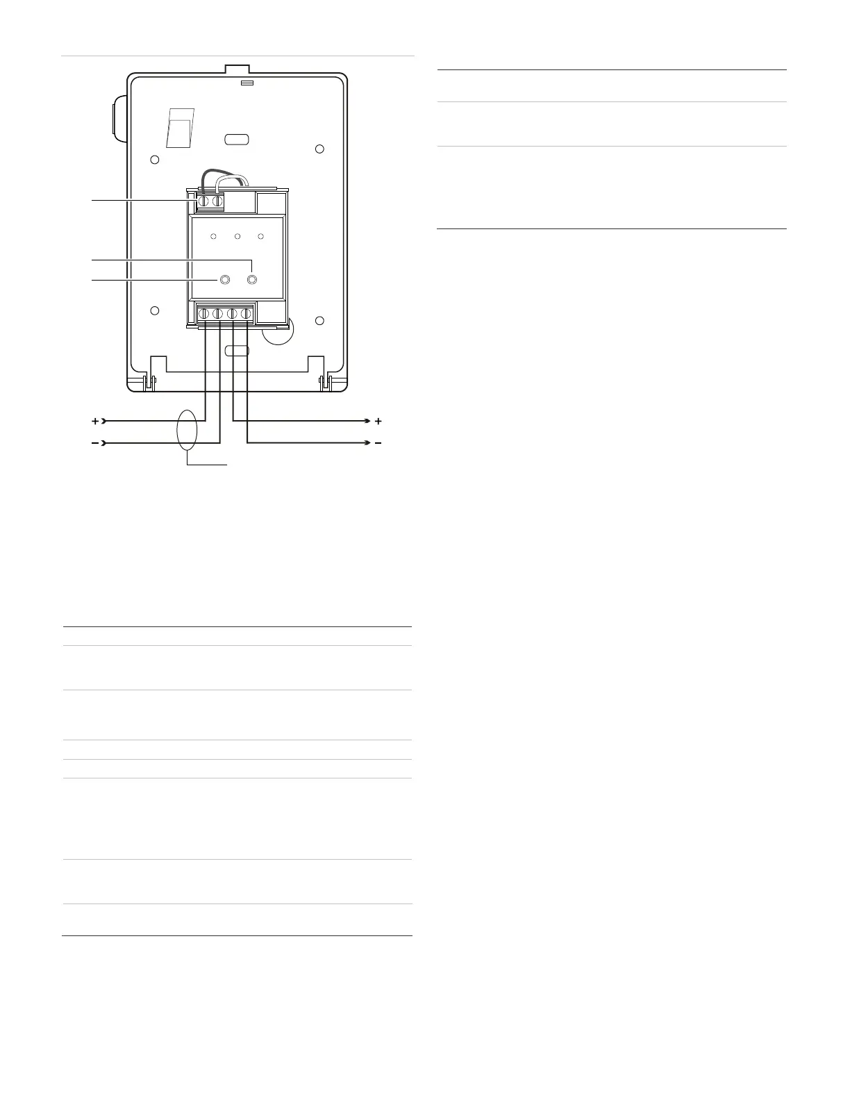
Figure 2: Wiring diagram (rear view)
(1) Factory connections — do not alter
(2)
Green LED (normal)
Red LED (alarm/active)
Signaling line circuit (SLC) from previous device
Signaling line circuit (SLC) to next device
All wiring is power-limited and supervised. Refer to the Signature
Controller Module installation sheet for wiring specifications.
Specifications
15.20 to 19.95 VDC
Standby
Activated
250 µA
400 µA
12 to 18 AWG (1.0 to 4.0 mm²).
16 and 18 AWG (1.0 and 1.5 mm²) are
preferred
Double action, pull lever
High impact plastic with steel backplate
Compatible electrical
boxes
North American 2-1/2 in. (64 mm) deep
single-gang box
Standard 4 in. square box 1-1/2 in. (38 mm)
deep box with single-gang cover
276B-RSB red surface mount box
Temperature
Relative humidity
32 to 120°F (0 to 49°C)
0 to 93% noncondensing
P/N 276-GLR (pkg. 20 rods)
Regulatory information
This device meets the ADA requirements for
manual pull stations.
To meet CAN/ULC-S527 ESD requirements, the
device must be mounted in a grounded metal
backbox.
This device complies with part 15 of the FCC
Rules. Operation is subject to the following two
conditions: (1) This device may not cause harmful
interference, and (2) this device must accept any
interference received, including interference that
may cause undesired operation.
Contact information
For contact information, see www.est-fire.com.
© 2014 UTC Fire & Security Americas Corporation, Inc.
All rights reserved.
(6)
TB1
(1)
(2)
(3)
4
3
2
1
(4) (5)

 Loading...