2 / 4 P/N 387021P-EN • REV 12 • ISS 23JUL13
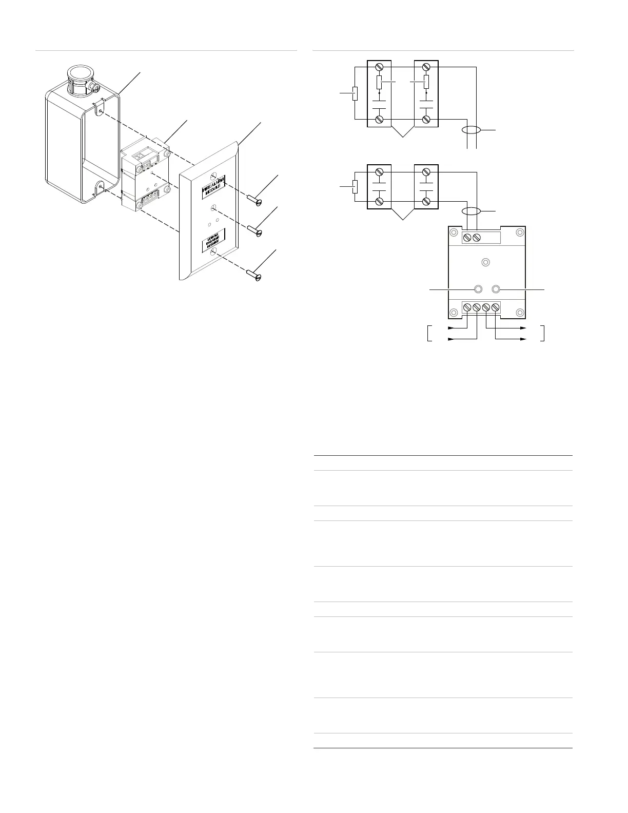
Figure 1: Mounting the SIGA-CT1 module
(1) Compatible electrical box
(2)
SIGA-CT1 module
(3) Wall plate, white (single-gang)
(4) #6-32 × 5/8 in. (16 mm) screw
(5)
#4 × 1/2 in. (13 mm) screw
Wiring
Wire in accordance with applicable requirements of the latest
editions of the local codes and standards and the local
authority having jurisdiction.
Note: When stripping wire ends, exposing more wire may
cause a ground fault; exposing less wire may result in a faulty
connection.
To wire the module:
1. Verify that all field wiring is free of opens, shorts, and
ground faults.
2. Strip 1/4 in. (about 6 mm) from the ends of all wires that
connect to the terminal block of the module.
3. Make all wiring connections as shown in Figure 2.
Notes
• Refer to the Signature loop controller installation sheet for
SLC wiring specifications for additional details.
• All wiring is power-limited and supervised.
• A test resistor is supplied with the SIGA-CT1 to prevent
trouble signals on unused circuits during installation.
When connecting field wires, remove the test resistors and
install a UL/ULC Listed 47 KΩ EOLR at the end of the
circuit.
Figure 2: Wiring diagram
(1) EOL resistor (PN EOL-47)
(2)
22 kΩ resistor for use with
personality code 18
Typical NO initiating device
Max. 10 VDC @ 350 µA
(5) Red LED (alarm/active)
(6) Green LED (normal)
(7)
Signaling line circuit (from
previous device)
Signaling line circuit (to next
device)
Specifications
15.20 to 19.95 VDC
Standby
Activated
300 µA
450 µA
10 kΩ
Initiating device circuit (IDC)
EOL resistor value
Circuit resistance
Circuit capacitance
47 kΩ, UL/ULC Listed
50 Ω (25 Ω per wire), max.
0.1 µF max.
Signaling line circuit
Notification line circuit
Class A, Style 6 or Class B, Style 4
Class B, Style B
12 to 18 AWG wire (0.75 to 2.5 mm²)
Compatible electrical boxes
2-1/2 in. (64 mm) deep single-gang
box; 4-in. square box 1-1/2 in (38 mm)
deep with single-gang cover
Requirements
Minimum (W × H × D)
Plastic box with cover plate, no gaps or
unused holes
2.4 × 3.5 × 1.5 in. (60 × 85 × 38 mm)
rating environment
Temperature
Relative humidity
32 to 120°F (0 to 49°C)
0 to 93%, noncondensing
Storage temperature range
−4 to 140°F (−20 to 60°C)
7
8
12
3
4
+ +
– –
(1)
(3)
(4)
(6)
(8)(7)
(5)
(2)
(4)
(1)
(3)
 Loading...