For example, to simulate a flashing light with brightness 5 for the external load (AUX1). Write in the
CV 115 the value 5 + 32 = 37 to get that.
Switch-on-delay
If desired, you can determine for each of the 8 outputs, whether these switch on immediately or
delayed. This requires as shown in the table above, the value 64 to be added to the previous value of
the CV for the output. The exact time of the delay is randomly determined each time within the limits
defined in CVs 59 and 60.
Random light
If desired, you can determine for each of the 8 outputs, whether it after switching via a function key
it later goes randomly off again and later back on. For this purpose, the value 128 must be added to
the previous value of the CV for the output as shown in the table above. When and for how long the
output is then turned off, respectively, is determined by CVs 61 and 62.
Start blink number of neon light
In CV 63, you can determine how often a neon lamp flashes before it is permanently switched on.
Period for flashing lights
If the function flashing light or strobe was selected for an output, the period (and thus the blink rate)
is stored for all outputs relating it in CV 112.
Function mapping
The outputs can be freely assigned to function keys. For each of the functions F0 to F20 of the digital
system a decoder CV is responsible. For the function F0 forward, it is the CV33, for the function F0
backward it is the CV34 and so on up to CV136 for the F20 function. The value in this CV determines
which function output reacts to which function.
Example: In CV 35 a value of 4 specifies that the function output AUX1 for forward travel corresponds
to Function 1.
What values must be entered in order to assign the functions to function outputs, can be seen in the
next table:
Search in the table the intersection between
the desired function ine and•
the column of the desired function output.•
Shown is the number that should be entered in the relevant CV for the desired assignment. The
factory settings are shown in bold. If a function button should switch more outputs, simply add the
values of the desired functions.
Decoder reset
You can always reset the decoder to the factory settings.
Write a value of 08 to CV 08.
Firmware update
The interior lighting strip software can be updated at any time, to correct bugs or retrofit new func-
tions. For that you will need the ESU LokProgrammer 53451/53452 with the most recent PC software
for it. During the writing of parameter the firmware will be updated when appliccable.
Technical data
List of all supported CVs
Name Description Brightness Mode Dealy on Random light
Dimmer Fast light on and off 0 - 7 + 0 + 64 + 128
Zoom Slow dimming of lights off and on 0 - 7 + 8 + 64 + 128
Neon light Neon light simulation 0 - 7 + 16 + 64 + 128
Defective
neon light
Defective neon light, flickering 0 - 7 + 24 + 64 + 128
Flashing light phase I Output flashes with adjustable frequency 0 - 7 + 32 + 64 + 128
Flashing light phase II Output flashes with adjustable frequency 0 - 7 + 40 + 64 + 128
Strobe Flashing light with adjustable frequency 0 - 7 + 48 + 64 + 128
Flickering light Flickering light simulation 0 - 7 + 56 + 64 + 128
CV Function
Front
light
Rear
light
AUX1
LED
Group „A“
LED
Group „B“
LED
Group „C“
LED
Group „D“
LED
Group „E“
33 F0 forward 1 2 4 8 16 32 64 128
34 F0 reverse 1 2 4 8 16 32 64 128
35 F1 forward 1 2 4 8 16 32 64 128
36 F2 1 2 4 8 16 32 64 128
37 F3 1 2 4 8 16 32 64 128
38 F4 1 2 4 8 16 32 64 128
39 F5 1 2 4 8 16 32 64 128
40 F6 1 2 4 8 16 32 64 128
41 F7 1 2 4 8 16 32 64 128
42 F8 1 2 4 8 16 32 64 128
43 F9 1 2 4 8 16 32 64 128
44 F10 1 2 4 8 16 32 64 128
45 F11 1 2 4 8 16 32 64 128
46 F12 1 2 4 8 16 32 64 128
47 F1 reverse 1 2 4 8 16 32 64 128
129 F13 1 2 4 8 16 32 64 128
130 F14 1 2 4 8 16 32 64 128
131 F15 1 2 4 8 16 32 64 128
132 F16 1 2 4 8 16 32 64 128
133 F17 1 2 4 8 16 32 64 128
134 F18 1 2 4 8 16 32 64 128
135 F19 1 2 4 8 16 32 64 128
136 F20 1 2 4 8 16 32 64 128
Power supply 4-24V 0 / ~
Modes
DCC with 14, 28 and 128 speed steps (automatic detection)
Motorola® data format
Analogue DC operation
Constant brightness from 6V input voltage
Current consumption
50708: about 25mA
50709: about 35mA
Dimensions 255mm x 7mm (decoder range : 8.1mm)
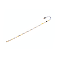
50708, 50709 Digital Car-Interior lighting
P/N 00815-15732
CV Name Description Range Value
1 Loco adress Adress 1 - 127 3
8 MakerID Maker (ID) ESU – Writing 8 into CV8 will reset to factory values 151 151
17
18
Long loco adress Long adress
CV 17 holds the higher Byte (Bit 6 and Bit 7 alwas set), CV18
holds the lower Byte. Only used when the function is activated
in CV 29 (See there)
128 -
9999
192
19 Consist Address Additional address for consist operiation. Value 0 or 128 means
consist is disabled
0-255 0
29 Configuration register The most complex CV within the DCC standards.
This register contains important information, some of which are
only relevant for DCC operation
30
Bit Function Value
0 Normal direction
Reversed direction
0
1
1 14 speed steps in DCC operation
28 or 128 speed steps in DCC
0
2
2 Disable Analog operation
Analog operation enabled
0
4
5 short addresses (CV 1) in DCC mode
long addresses (CV 17+CV18) in DCC
0
32
49 Extended Configuration Additional important settings for Decoders 0 - 255 19
Bit Description Value
3 Märklin® 2. Adress Disable
Märklin® 2. Adress Enable
0
8
4 Auto Speed step detection DCC OFF
Auto Speed step detection DCC ON
0
16
59 Delay lower limit Minimal value of switch-ON. Delay Multiple of 0.25 Sec. 0 - 64 0
60 Delay upper limit Maximal value of switch-ON. Delay Multiple of 0.25 Sec. 0 - 64 8
61 Random time lower limit Minimum time on for output, using random timing. Multiple
of 0.25 Sec.
0 - 64 10
62 Random time upper limit Maximum time on for output, using random timing. Multiple
of 0.25 Sec.
0 - 64 20
63 Start flash number Neon simulation Number of start flashes for Neon light simulation 0 - 15 020
112 Blinking frequency Blinking frequency of Strobe effects. Always a multiple of 65.536
milliseconds.
4 - 64 16
113 Front light configuration Output configuration „Front light“ 0 - 255 15
114 Rear light configuration Output configuration „Rear light“ 0 - 255 15
115 AUX1 Output configuration Output configuration „AUX1“ 0 - 255 15
116 Output configuration LED 1-3 Output configuration „LED 1-3 Group A“ 0 - 255 15
117 Output configuration LED 4-5 D Output configuration „LED 4-5 Group B“ 0 - 255 15
118 Output configuration LED 6-7 Output configuration „LED 6-7 Group C“ 0 - 255 15
119 Output configuration LED 8-9 Output configuration „LED 8-9 Group D“ 0 - 255 15
120 Output configuration LED 10-11 Output configuration „LED 10-11 Group E“ 0 - 255 15
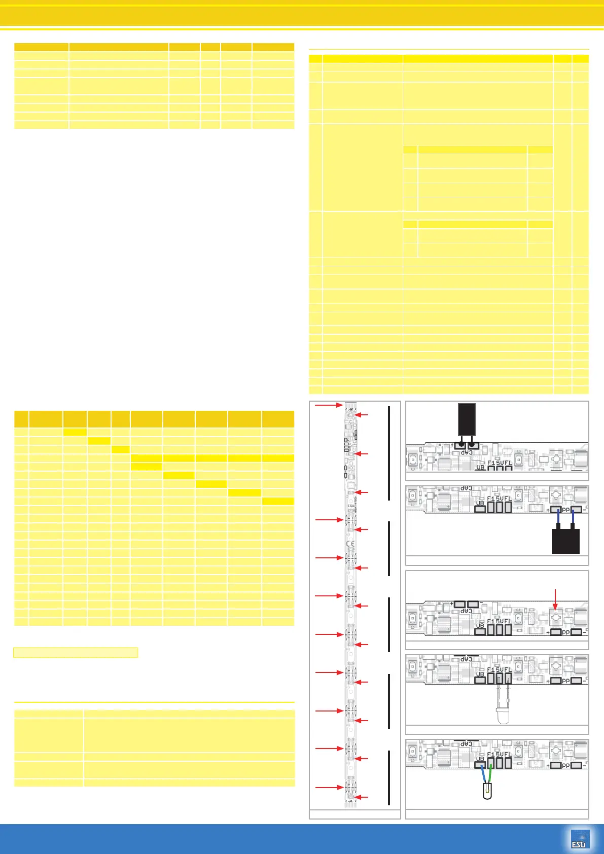
Cut here
Cut here
Cut here
Cut here
Cut here
Cut here
Cut here
Cut here
Ponts for
connection
power supply
~ ~
LED 1
LED 2
LED 3
LED 4
LED 5
LED 6
LED 7
LED 8
LED 9
LED 10
LED 11
A
B
C
D
E
Fig. 1
Fig. 2
Fig. 3
Fig. 4
Fig. 5
Fig. 6
1000uF
35V
- +
- OG +
S 5.5V
0.1F
Brightness controlled by turning pot.
Attention: Use small screwdriver!
+
Only use LED!
Max. current 20mA.
Series resistor is already
installed
Use cap for at least 35V!
Use only ESU “PowerPack”50706!
 Loading...