P/N 00815-15732
50708, 50709 Digital Car-Interior lighting
Warnings
The LED interior lights are intended for installation in model railroad cars. •
All connection work should be carried out only with the power turned off. •
Adhere to the principles as outlined in this manual. •
Protect from moisture and humidity, as well as mechanical force or pressure. To avoid damage do not bend •
the lights unnecessarily.
Be sure when assembling the vehicle that no cables are pinched or metal parts of the car are touched or •
short circuits will occur.
It is easy to vary the color of the LEDs, and their brightness within the manufacturer‘s tolerances.•
Main Features
The ESU LED car interior lights provide you with 11 LEDs for uniform illumination in your cars. The
integrated multi-protocol decoder can be used with DCC or Motorola® and works on analogue DC
layouts. The operating mode is automatically recognized. The following characteristics distinguish the
interior lights specifically:
11 warm white LEDs (50708).•
11 yellow LEDs (50709).•
Built-in constant voltage source for uniformly bright light, regardless of the track voltage. •
Individually adjustable brightness. •
The lighting strip can be shortened at eight points. •
A built-in buffer capacitor that bridges small power interruptions. •
Optionally, 50706 energy storage (a „power pack,”) can be connected to bridge longer interrup-•
tions.
The 11 LEDs are divided into five groups, each of which is individually switchable. •
Each interior lighting strip comes with a red rear light, which can be switched in relation to the •
direction of travel.
Connection for a directional white front light (LED only, up to 20mA). •
Connection option for further external loads (up to 100mA). •
Different lighting effects such as soft dimming, neon effect, defects or neon lighting, battery light, •
can be assigned to each group individually.
Delay and random lights can be selected individually. •
Installation of Car lighting
LED - Groups
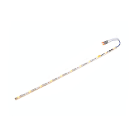
The 11 integrated LEDs as shown in Fig. 1 are divided in the 5 groups „A“ to „E“ and connected
directly to an output of the integrated function decoder. Each group can be switched individually and
provided with light effects.
Shortening the Car lighting
The interior light strip should first be cut to the required length. The PCB can be shortened at one of
the points marked in Fig. 1. Cut along the dotted line with a small hacksaw. The remaining pieces can
be used elsewhere for your own purposes.
IMPORTANT: Be careful when cutting that you do not damage any components on the pads and
PCB.
Power supply
The pre-wired power cable may be cut to the required length. All connection points left and right
are already connected in the circuit board. Therefore, one cable per side is sufficient. One side is
connected to the left wheel (or with the car ground/mass for Märklin models), the other side to the
right wheel of the car (or the Center rail for Märklin models). The polarity is irrelevant; each strip has
an internal rectifier.
ESU offers SKU 50707 “wheel pickups” appropriate for almost all cars. For cars with current carrying
couplers, the two supply lines alternatively connect with the coupling contacts.
The easiest way to attach the PCB under the car roof is double-sided tape. You can also look in the
interior design for suitable anchor points.
Connecting a buffer capacitor
An integrated Tantalium capacitor eliminates flickering illumination during short power interruptions.
If there is a poor connection situation, an additional buffer capacitor of at least 35V and a capacity of
4700 uF maximum can be connected to the position shown in Fig. 2.
Connecting a PowerPack
If you would you like to have the lights on (at red signals, for example), even during a prolonged
power failure, a simple buffer capacitor is not sufficient. You can connect the high-energy storage
available under the order number 50706. In Fig. 3 the corresponding connecting points are marked
with „Power Pack +“ and „Power Pack -“.
Make sure the polarity is correct, otherwise both the Power Pack and the lighting strip may be des-
troyed!
Included rear lights
Each lighting strip has red rear lights that are already soldered on. These work directionally in both
digital and analog model. If the rear lights are not needed, you should remove them. The rear lights
can be used at both ends.
Therefore, the wires can be re-soldered on the other end. When re-soldering pay attention to the
correct polarity.
Brightness Control
By means of the control shown in Fig. 4, the maximum brightness of all LEDs together can be adjusted
as desired. The brightness can be further reduced individually by programming.
Optional front light
For operation in Control/Cab car, as shown in Fig. 5, a white front light can be added. Only white or
yellow LEDs with a maximum current consumption of 15mA may be used. A series resistor is already
installed. The front light works like the rear light, directionally.
External load (AUX1)
To switch external loads (eg toilet lighting, destination signs, etc.) a separate transistor output with
a maximum current of 100mA is available. It is shown in Fig. 6, and is preferably connected to the
voltage + U. A series resistor for LEDs is not installed. The U + voltage is not buffered by the power
pack and the control to adjust for brightness has no effect.
Operation
Digital operation
The interior lighting works with any digital system that uses either the DCC or the Motorola® format.
The decoder recognizes the protocol automatically
The default address is 03 with 28 speed steps (DCC).
F0 F0 turns on the red rear light (direction of travel)
F1 switches the external load (AUX1)
F2 switches all the LEDs together
F3 switches the LEDs 1-3 (group „A“)
F4 switches the LEDs 4-5 (group „B“)
F5 switches the LEDs 6-7 (group „C“)
F6 switches the LEDs 8-9 (group „D“)
F7 switches the LEDs 10-11 (group „E“)
Analog operation
The interior lighting can also be used with analog DC power supplies. In this case, the factory setting is
set up so that all the LEDs light up(the red rear lights as well as any installed front light.) These respond
to the direction of travel with DC power supplies.
Customize decoder settings
All adjustable parameters of the interior lights are in so-called CVs („Configuration Variables „) ar-
ranged according to the NMRA DCC standards. These can be selectively modified with your control
system.
Programming with DCC systems
The interior lighting strip knows all programming methods of the NMRA. Use either the Programming
track or the main track programming („Programming on Main“). Note the relevant section in the
manual of your Command Station.
Connect to AUX1 a load of 60mA to 100mA , in order to read CVs!
Programming with Märklin®6021
The Märklin® central unit 6021 works differently: Since it does not comply with the NMRA DCC
standards, the interior lighting start a special, obligatory programming procedure. Reading of values
is not permitted.
There are two modes:
In the short mode parameters with a number below 80 can be set provided the desired value is •
also lower than 80.
In the long mode, all parameters with values from 0 to 255 are adjustable. Since the display of •
the 6020 /6021 is limited to two-digit numbers, values must be split and entered in two separate
steps.
Changing the Programming Mode
Enter the programming mode with the 6020/6021:
The throttle must be set to „0“. No other locomotives may be on on the layout. Watch out for flashing
signals of the locomotive!
Press the „Stop“ and „Go“ buttons of the 6021 simultaneously until a reset has been triggered •
(alternately pull the mains plug of the transformer). Press the „Stop“ button in order to switch
off the track voltage. Enter the current decoder address. If you do not know the current address,
simply enter „80“.
Activate the change-of-direction button (turn the throttle knob to the left beyond the arrestor until •
you hear a click sound), hold it in this position and then press the „Go“ button
Please bear in mind that the 6020/6021 only permits you to enter values from 1 to 80. The value 0 is
missing. Always enter „80“ instead of „0“.
Short mode
The decoder is in the short mode (the headlights flash periodically in brief intervals).
Now enter the number of the CV that you want to adjust e.g.: „01“. Always enter this number •
with two digits.
For confirmation activate the change-of-direction routine (now the lights flash twice very quickly).•
Now enter the new value for the desired CV, e.g.: 15 (two digits). •
For confirmation activate the change-of-direction routine (now the lights light up for about one •
second).
Then you can enter other CVs as desired.•
Selecting „80“ allows you to exit the programming mode. Alternately you can switch off the track •
voltage and then on again (press the „Stop“ button on the 6021, then the „Go“ button).
Long mode
You access the long mode by entering the value 07 in CV 07 while in the short mode. The decoder
confirms the change to the long mode by slowly flashing lights.
Enter the hundred-digit and the ten-digit (decade) of the CV that you want to change. Example: If •
you want to adjust CV 124, you enter „12“.
For confirmation activate the change-of-direction routine (now the lights flash periodically: long – •
short – long – short - etc.)
Now enter the unit of the CV („04“ in this example). •
For confirmation activate the change-of-direction routine. Now the decoder expects the entry of •
the CV value. The lights flash periodically: long – short – short).
Now enter the hundred-digit and the ten-digit (decade) of the new CV value (as a two-digit num-•
ber). Example: You want to write the value 135. Therefore, you enter „13“.
For confirmation activate the change-of-direction routine. Now the lights flash periodically: long – •
short – short – short).
Now enter the unit of the new CV value as a two-digit number („05“ in this example). •
For confirmation activate the change-of-direction routine (now the lights light up for about one •
second).
Now you can adjust more CVs in long mode.•
Exit the long mode by switching off the track voltage and then on again (press the „Stop“ button •
on the 6021, then „Go“ ).
Programming with LokProgrammer
Using the separately offered ESU LokProgrammer 53451/53452, you can comfortably change your
interior lighting CVs right on your computer screen with a mouse click. This will save you from a search
for CV numbers and values.
Setting parameters
Function outputs
At each function output light effects and special effects can be set. For each output a CV is set
up(CV113 - CV 120, see table), in which the desired brightness value and the code for the desired
mode is stored.