EasyManua.ls Logo

Et system MD2010 User Manual

Et system MD2010
4 pages
To Next Page IconTo Next Page
Page #1 background imageLoading...
Page #1 background image
MD2010
METAL LOOP DETECTOR
Sensing loop position:
A safety loop should be positioned where the largest amount of metal of the vehicle will be present
when that vehicle is in the path of the moving gate, door or boom pole. Be aware that metal gates,
doors or poles could activate the loop detector if they pass within range of the sensing loop.
A free exit loop should be positioned +/- one and a half car lengths away from the gate, door or
boom pole, on the approach side for traffic exiting.
In cases where more than one loop is installed ensure there is at least 2m between the sensing loops
to prevent cross-talk interference between the loops. (Also see Dip-switch 1 option and number of
turns around the loop below)
Sensing loop dimensions and shape :( Figure 1)
A square or rectangular slot of +/- 4mm should be cut into the road surface 30 – 50mm deep.
The recommended minimum distance between either of the parallel sides is 1m.
Cross cut the corners by 45º to prevent damage to the cable as it passes around the corners.
The feeder slot will need to be wider to allow for the required twisting of the feeder.
Sensing loop wire:
Single length copper “Panel Flex” (Stove wire)
Silicone insulated
Minimum cross section - 1.5mm
2.
Joints in the wire are not recommended. If made they should be soldered and weatherproofed
sufficiently.
Number of turns around the loop:
Loop circumference 7-10m - 3 turns
Loop circumference >10m - 2 turns
Loop circumference < 7m - 4 turns
In cases where 2 loops are adjacent to each other, use 3 turns in one and 4 turns in the other to help
prevent cross-talk interference.
Detector position and installation:
Install the detector in a weatherproof housing.
The detector should be as close to the sensing loop as possible.
Installation summary:
Run the single length of wire from the detector, around the loop 3 times (see “Number of turns of loop” above)
and then back to the detector. The 2 ends running to the loop and returning from the loop of the same length
of cable is known as the feeder and must be twisted together 20 – 30 times per meter. The twisting will shorten
the feeder, so allow excess cable when starting out from the detector and on the return from the loop.
Question and Answer IconNeed help?

Do you have a question about the Et system MD2010 and is the answer not in the manual?

Et system MD2010 Specifications

General IconGeneral
BrandEt system
ModelMD2010
CategorySecurity Sensors
LanguageEnglish

Summary

Metal Loop Detector Installation and Sensing Loop Setup

Sensing Loop Position Guidelines

Proper placement of the safety and exit loops for vehicle detection and traffic flow.

Sensing Loop Dimensions and Shape

Specifications for cutting loop slots and ensuring minimum distances for parallel sides.

Sensing Loop Wire Specifications

Details on wire type, insulation, cross-section, and recommended joint treatment.

Loop Turns and Feeder Requirements

Guidance on the number of turns based on loop circumference and feeder twisting.

Detector Installation Location

Recommendations for installing the detector in a weatherproof housing near the loop.

MD2010 Dip-Switch Configuration Options

Frequency Setting (Dip-switch 1)

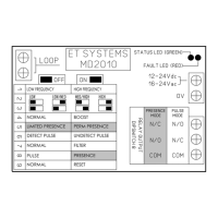
Configures loop frequency (Low/High) to minimize crosstalk between multiple loops.

Sensitivity Settings (Dip-switches 2 & 3)

Adjusts sensitivity levels (Low to High) to trigger the detector based on metal presence.

Boost Mode Activation (Dip-switch 4)

Enables temporary high sensitivity for vehicles with varying undercarriage height.

Presence Mode Selection (Dip-switch 5)

Determines if the relay remains active for permanent or limited presence of a vehicle.

Relay Response Timing (Dip-switch 6)

Configures relay activation on detection (Pulse on Detect) or non-detection (Pulse on Undetect).

Filter Functionality (Dip-switch 7)

Adds a 2-second delay to prevent false triggers from small or fast-moving objects.

Pulse vs. Presence Mode (Dip-switch 8)

Selects between pulse mode relay activation or continuous presence mode.

Detector Reset Procedure (Dip-switch 9)

Resets the detector after changing dip-switch settings or for loop testing.

Troubleshooting Loop Faults and Indicator Signals

Faulty Loop Diagnosis (Below 20kHz)

Identifies open loop faults and provides LED/buzzer indications and corrective actions.

Faulty Loop Diagnosis (Above 120kHz)

Identifies short-circuited loops and provides LED/buzzer indications and corrective actions.

Good Loop Indication

Details on how the Detect LED, Fault LED, and buzzer indicate a good loop frequency.

Power Up/Reset LED and Buzzer Indications

Explains the meaning of LED flashes and buzzer tones upon detector initialization.