Do you have a question about the ETC Unison ERn2-W and is the answer not in the manual?
Overview of ERn enclosure types and their use in Unison systems.
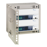
Details the ERn2 enclosure's processor and module support.
Describes the ERn4 enclosure's capacity for processors and repeater modules.
Describes the P-ACP, its features, and network capabilities.
Explains the P-SPM's function in powering Unison control stations.
Details the P-REP's role in extending the system station bus length.
Describes the P-DREP's extended bus capabilities for two segments.
Details the ERn-NET module's ports and PoE capability.
Explains the UBPO's backup power duration during outages.
Details the URTO kit's temporary power provision during outages.
Explains the ERn-BM's purpose for filling empty module spaces.
Describes the ERn-RPS's function in case of primary power supply failure.
Explains the 'Note' symbol for supplemental hints and information.
Explains the 'Caution' symbol for potential negative consequences.
Explains the 'Warning' symbol for potential harm or damage.
Explains the 'Risk of Electric Shock' warning for electrical hazards.
Provides contact details for ETC in the Americas region.
Lists contact information for ETC in the Asia region.
Provides contact details for ETC in France.
Lists contact information for ETC in the United Kingdom.
Provides contact details for ETC in Germany.
Outlines steps for checking the shipment for completeness and damage.
Emphasizes the need for an accessible power disconnect device.
States the maximum current draw and allowable protection device ratings.
Provides guidance on selecting a suitable location for wall-mount installation.
Details necessary front and side clearance for proper operation and airflow.
Lists the physical dimensions and weights for ERn2 and ERn4 enclosures.
Specifies environmental conditions like temperature and humidity for installation.
Discusses conduit knockouts and separate routing for power and control wires.
Mentions single-phase power input for the ERn enclosure.
Illustrates a typical system riser diagram with ERn and other components.
Explains LinkConnect, DMX, and Auxiliary 24 VDC wiring types and limitations.
Provides instructions for mounting the ERn enclosure to a wall.
Details precautions and procedures for running conduit and wiring.
Explains how to remove modules for easier conduit and wiring access.
Guides on planning wire entry, removing knockouts, and installing fittings.
Instructs on safely connecting line, neutral, and ground wires to the power block.
Explains how to connect low-voltage data to the left and right I/O boards.
Details terminations for 24 VDC, LinkConnect, ERn-RPS, and Ride Thru/Batt.
Mentions DMX preparation and termination kit instructions.
Illustrates DMX termination using screw terminals for Belden 9729 cable.
Shows DMX termination using IDC connectors for Belden 1583A cable.
Guides on connecting LinkConnect stations and sensors to the P-ACP.
Detailed steps for terminating LinkConnect wiring to the I/O board.
Explains connecting auxiliary power using the ten-position pluggable connector.
Steps for terminating auxiliary power wiring to the right I/O board.
Explains DMX termination switches and their positions (Source, Off, End).
Details terminations for Ethernet, RS-232, and contact inputs/outputs on the left I/O board.
How to connect to external devices using the RS-232 interface.
Instructions for connecting network interface using the RJ-45 connector.
Describes interface with external devices via contact closure on the left I/O.
Steps for wiring contact closure inputs to the left I/O board.
Steps for wiring contact closure outputs to the left I/O board.
Emphasizes safety checks before applying power to the enclosure.
Guides on checking resistance between line, neutral, and ground busses.
How to check input voltages with a DVM before installing modules.
Steps for installing P-ACP, P-SPM, and other option modules.
Continues installation of modules like ERn-NET, ERn-RPS, and blank modules.
Lists available Unison ERn options like RideThru, BatteryPack, Ethernet Switch.
Instructions for installing the URTO kit for temporary power during outages.
Details module removal and board mounting for URTO installation.
Explains how to connect the URTO wiring harness to the I/O board.
Guides on installing the UBPO kit for backup power during outages.
Steps for physically installing the BatteryPack unit onto the ERn enclosure.
Details installation of P-REP or P-DREP modules in ERn4 top slots.
Steps for terminating LinkConnect wiring for repeater modules in ERn4.
Continues LinkConnect wiring termination for repeater modules.
Explains terminating auxiliary power wiring for repeater modules.
Describes LEDs indicating status of auxiliary power and LinkPower network.
Guides on installing the ERn-RPS for redundant power.
Details installing the ERn-NET module in the bottom option slot.
Steps for installing the Ethernet patch panel and switch panel.
Instructions for wiring CAT5e cable to the Ethernet Switch Module.
Explains the LEDs indicating main power, data, and PoE status.
| Type | Enclosure |
|---|---|
| Model | ERn2-W |
| Material | Steel |
| Color | White |
| Weight | Varies depending on modules installed |
| Rackmount | No |
| Mounting | Wall mount |
| Compatibility | Unison control systems |
| Power Supply | External |