A
A
B
B
CC
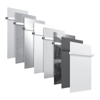
HOLE CLEARANCES FOR VERTICAL WALL INSTALLATION
Connection line Connection line
Type Installation Width A mm Distance B mm Distance C mm Mounting brackets
LAVA
®
BATH 2.0 / BATH DYL 350 W senkrecht 630 406 448 2
LAVA
®
BATH 2.0 400 W senkrecht 500 406 406 2
LAVA
®
BATH 2.0 / BATH DYL 500 W senkrecht 630 406 448 2
LAVA
®
BATH 2.0 600 W senkrecht 500 406 406 2
LAVA
®
BATH 2.0 / BATH DYL 700 W senkrecht 630 406 448 2
LAVA
®
BATH 2.0 PURE 350 W senkrecht 620 406 448 2
LAVA
®
BATH 2.0 PURE 500 W senkrecht 620 406 448 2
LAVA
®
BATH 2.0 PURE 700 W senkrecht 620 406 448 2
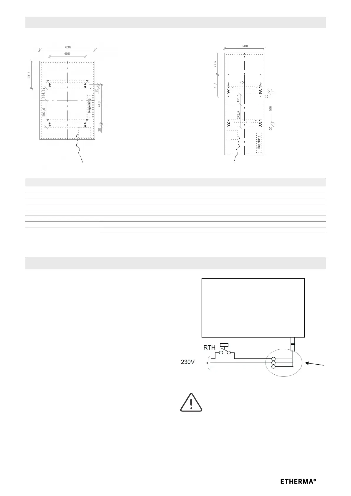
ELECTRICAL CONNECTION
The heater is designed for permanent connection to a wall jack
or socket.
The device is connected to the AC mains system by putting the
power cord into a connection socket.
NOTE
The connecting cable can be extended using a cable of the
H05VV-F3G1,50 type. A direct connection to a permanently laid
cable may only be implemented up to a diameter of 1.5 mm²
(e.g. NYM-J3G1,5 mm²). The length of the connecting cable
must be between 1.0 and 1.9 m.
An all-pole disconnecting device with a minimum contact open-
ing width of 3 mm has to be mounted into the xed electrical
installation in compliance with the installation regulations.
HEATING MODE
The heater is operated by means of direct connection via
switch, via an external room thermostat, via timer or controller
directly on the device or via a radio receiver in connection with a
radio-controlled room thermostat. These items can be ordered
as accessories. Please observe the operating instructions
of the respective product.
Dimensional drawing: Connection circuit diagram
ATTENTION: If the main cable to the device is dam-
aged, it must be replaced immediately by a spe-
cialist.
11
 Loading...