Do you have a question about the ETL ATS 400 and is the answer not in the manual?
Explains warning symbols for danger, caution, and information for safe operation.
States operations are allowed only for qualified or trained personnel.
Emphasizes observing relevant prescriptions and protective measures for all operations.
ETL Prüftechnik disclaims liability for operator misuse or unauthorized modifications.
Warns to avoid transport damage and specifies palletized transport.
Operator must follow manual and EN 50191 warnings for riskless operation.
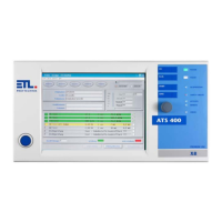
High-quality CE Testing System for checking electric safety of electrotechnical products.
Automatic Test System ATS 400 is valid for all products of the Series 400.
DANGER: Operations must adhere to regulations; consult safety information.
Regular maintenance is required for the safety circuit, detailed in relevant chapters.
Lists included items: power cable, manual, safety circuit plug, warning lamp plug.
Defines key terms like Baseboard, FAIL SAFE, Current enabling circuit, Safety circuit.
Activates the test system; can be an illuminated or key switch button.
Used for navigation in menus; push for acknowledgment, swivel for movement.
Buttons for PASS, FAIL, and START to control test execution and results.
Shows status like PASSED, FAILED, IN OPERATION, SAFETY CIRCUIT, POWER ON, KEYLOCK, REMOTE, ERROR.
Front panel display varies by model; X2/X6 closed, X4/X5/X8 touchscreen.
Describes four types: Remote, Stand-Alone, PC-Inside, and High-End.
Digital I/O for remote control via PLC or operation interface; 25-pole SUB-D connector.
Optional interface for query of limit switches and setting outputs; 25-pole SUB-D connector.
ETL/User Interface supply 24V for external devices (up to 2A). Digital outputs are source, inputs are sink.
Optional interface for analogue sensor signals and rotational speed signals; 15-pole SUB-D connector.
Serial interface for PC, log printer, or PLC connection; 9-pole SUB-D plug.
Interface for system extensions, e.g., external relay matrix operation.
Two potential-free high voltage outputs for contacting test objects; double pole HVS06C jacks.
For contacting test objects via probe with start button and result-LEDs.
Connections and explanations for SHK-NG found in chapter 7 Safety circuit.
Redundant earthing (PE): Connect with 4mm² cable to separate grounding point to avoid damage.
Explains the safety circuit's function, configurations, and support for warning lights.
Lists safety standards met (EN61508, ISO 13849) and achieved security levels.
Details the 10-pole LEMO socket connection for warning lamps.
Details the 10-pin LEMO socket connection for the safety circuit.
Wiring diagram for configuration 0; detected if no plug inserted, results in FAIL SAFE.
Wiring diagram for two-hand appliance; requires no actuation at power-on, has simultaneity monitoring.
Wiring diagram for protective door/test cage with 2 closers; simultaneity monitoring with 2.5 s.
Wiring diagram for protective door/test cage with antivalent contacts; simultaneity monitoring with 2.5 s.
Wiring diagram for protective door automation; simultaneity monitoring with 2.5 s.
Wiring diagram for check with test pistol; safety circuit opened/closed via LOCK button or ETL DataView.
Wiring diagram for smart switch; cross-circuit monitoring E5-E7 by intelligent switch.
Wiring diagram for protective door with guard locking & 2 NO contacts; release via output 01.
Wiring diagram for protective door with guard locking, potential-free contacts; release via output 01.
Wiring diagram for protective door with OSSDs; cross-circuit monitoring E5-E7.
Front LED indicates enabling circuits open/closed; flashes when safety circuit is in FAIL SAFE state.
If safety circuit enters FAIL SAFE state, it is indicated in the status bar of ETL DataView 3.
Dialog to display safety circuit status; accessed via Services -> Safety circuit in main menu.
Displays State machine, Configuration, FAIL SAFE, SC manually operated, Error info text, Reset SC.
Shows Safety relais states, State, Boot timeout, SC data timeout, CAN data timeout, FAIL SAFE, Boot Error.
Details Safety relais, Warning lamps (red/green), Configuration ready, Running OK, Lock open/closed.
Provides SC version, Slave present status, SC manually operated, Open lock, Warning lamp flashing, BB version, HW ID.
Debug options: Boot timeout, Restart SC, Data from SC, SC locked, Send debug data, Lock is open.
Accessory required for test cage or two-hand appliance.
Accessory required for protective door in automation solution.
Plug supplied as accessory; refer to Scope of Delivery.
Operate via ETL DataView 3, custom applications (DLL, LabVIEW), or serial interface/ASCII protocol.
Explains the structure of blink codes: 6 bits, synchronization, short/long signals.
Lists and explains blink codes for various errors like communication loss, overtemperature, and power failure.
Covers factory default settings with no output or tones.
'Enabled' output mode for test step control, active until the next test.
Configures test start modes (Button Start, Time-based) and associated parameters.
Settings for Safety Circuit activation and using the built-in buzzer.
Options for disabling signals, polarity control, lamp flashing, HV timing, and matrix control.
Setting to disable analog output of measurement and result values.
Provides specifications for power, display, dimensions, weight, interfaces, and connections.
Details test parameters, setup options, language selection, and information on measurement modules.
| Brand | ETL |
|---|---|
| Model | ATS 400 |
| Category | Test Equipment |
| Language | English |