SAFETY INSTRUCTIONS
SAFETY PRECAUTION
WARNING: Service should not be attempted by
anyone unfamiliar with the necessary precautions on this
unit.
The following are the necessary precautions to be
observed before servicing this unit.
1. Since the chassis of this unit could have a
hazardous potential to ground whenever the AC Adaptor
is plugged in (floating chassis), an isolation transformer
should be used during any dynamic service to avoid
possible shock hazard.
2. When replacing a chassis in the cabinet, always
be certain that all the protective devices are put back in
place. Examples of these items are: non-metallic control
knobs, insulating covers, shields, and isolation resistors,
capacitor networks etc.
3. Before returning the unit to the customer, always
perform an AC leakage current check on the exposed
metallic ports of the cabinet, as well as antennas,
terminals, screw heads, metal overlays, control shafts
etc. Be sure the unit is safe to operate without danger of
electric shock. Plug the AC adaptor directly into the AC
mains outlet (do not use a line isolation transformer
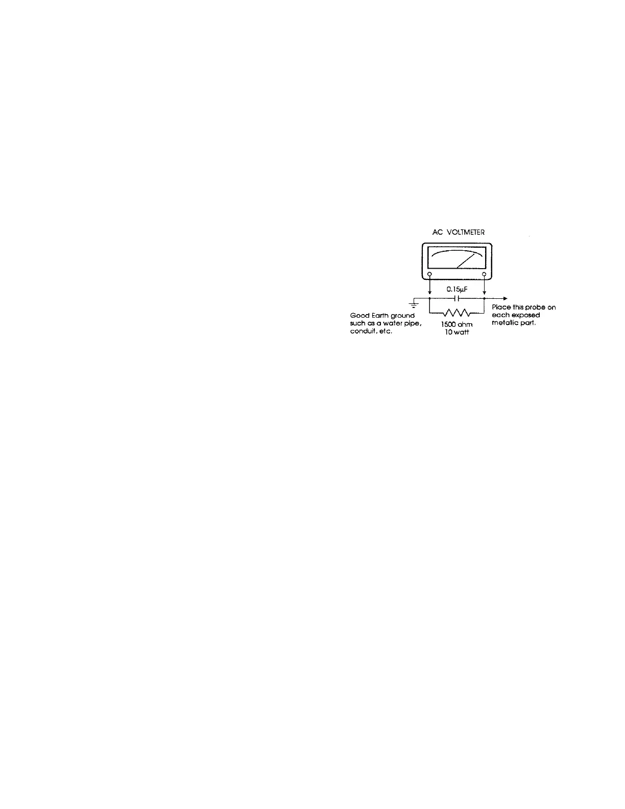
during this check). Use an AC voltmeter having 5000
ohms per volt or more sensitivity in the following manner:
Connect a 1500 ohm,10 watt resistor, paralleled by
a 0.15 mF, AC type capacitor, between a known good
earth ground (water pipe. conduit. etc.) and the exposed
metallic parts, one at a time. Measure The AC voltage
across the combination of 1500 ohms resistor and 0.15
mF capacitor. Reverse the AC plug at the AC outlet and
repeat AC voltage measurements for each exposed
metallic part. Voltages measured must not exceed 0.3
volts RMS. This corresponds to 0.2 milliamps AC. Any
value exceeding this limit constitutes a potential shock
hazard and must be corrected immediately.
PRODUCT SAFETY NOTICE
Many electrical and mechanical parts in this chassis
have special safety-related characteristics, These
characteristics are often passed unnoticed by a visual
inspection and the protection afforded by them cannot
necessarily be obtained by using replacement
components rated for higher voltage, wattage, etc.
Replacement parts with these safety characteristics are
identified on the schematic diagrams and board layout
drawings.
BEFORE ATTEMPTING SERVICE
CAUTION: UNPLUG RECEIVER'S AC ADAPTOR AND/OR REMOVE BATTERIES BEFORE PLUGGING IN CABLES
ON PRINTED CIRCUIT BOARDS AND OTHER COMPONENTS, THEN DOUBLE CHECK FOR CORRECT CABLE
POSITIONING BEFORE APPLYING POWER.
EVEN A MOMENTARY IMPROPER CABLE CONNECTION TO PRINTED CIRCUIT BOARDS OR OTHER
COMPONENTS CAN CAUSE WIDE SPREAD DAMAGE TO INTEGRATED CIRCUITS AND DISCRETE
COMPONENTS. NOTE: CABLES ARE NOT KEYED IN ALL CASES TO PREVENT IMPROPER INSERTION.
POWER MUST BE DISCONNECTED FROM RECEIVER'S AC ADAPTOR OR INTERNAL BATTERIES MUST BE
REMOVED TO PREVENT POSSIBLE DAMAGE WHEN INSERTING CABLES SINCE MANY CIRCUITS REMAIN
OPERATIVE WHEN THE POWER BUTTON IS "OFF". ALWAYS DOUBLE CHECK FOR CORRECT CABLE
POSITIONING BEFORE APPLYING POWER.
 Loading...