9
Assembly Instructions
Plug Connectors
Assembly instructions for metal-encapsulated round plug connectors
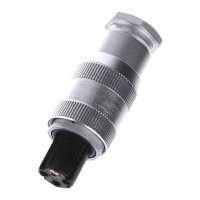
Assembling male socket SD and female socket
BD on the device
1. Screw the holder
into the PG thread of the
device. An O-ring serves as the seal.
2. Strip the insulation from the cable sheath and
exible wires in accordance with the corre-
sponding specications from the Stripping
length table.
3. Properly solder the exible wires to the corre-
sponding connections of the contact insert
.
Begin with the inner connections.
4. Route the ying leads through the holder
and to the device connection. Place the con-
tact insert
into the holder
and fasten it
using the retaining screw
.
5. For version BD: Slide the sealing ring
4
over
the contact insert
and into the retaining
screw
.
6. Any unconnected exible wires must be prop-
erly insulated (e.g. with shrinkable tubing) to
prevent arcing.
4
Stripping length [mm]
Plug connector
4-pin 7-pin 8-pin 12-pin 19-pin
Cable sheath 20 20 20 25 35
Flexible wires 3
SD
BD
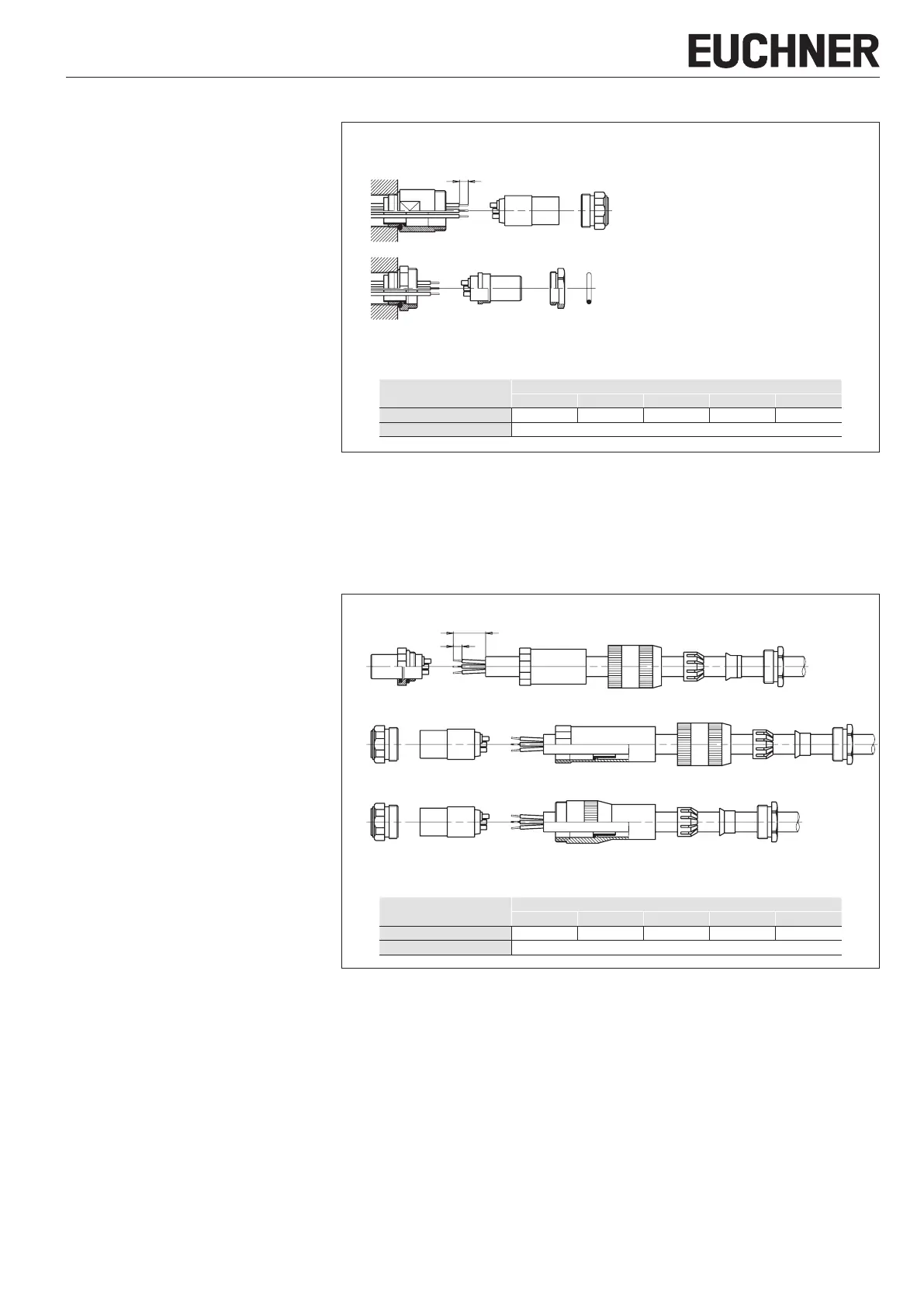
Assembling female plug BS, male plug SS and
coupling socket KD
1. Strip the insulation from the cable sheath and
exible wires in accordance with the corre-
sponding specications from the Stripping
length table.
2. Slide the parts
1
,
2
,
3
,
5
,
6
over the
cable in the specied sequence.
3. Properly solder the exible wires to the corre-
sponding connections of the contact insert
7
.
Begin with the inner connections.
4. Any unconnected exible wires must be prop-
erly insulated (e.g. with shrinkable tubing) to
prevent arcing.
5. For BS: Screw the sleeve
6
onto the contact
insert
7
.
Slide the clamping nut
5
over the sleeve
6
.
For SS: Place the contact insert
7
into the
sleeve
6
and fasten it using the retaining
screw
8
.
Slide the clamping nut
5
over the sleeve
6
.
For KD: Place the contact insert
7
into the
sleeve
6
and fasten it using the retaining
screw
8
.
6. Slide the clamping cage with seal
3
and
clamping ring
2
over the cable and into the
sleeve
6
and secure it with the pressure
screw
1
.
3
a
7 6 5 3 2 1
7 6 5 3 2 18
7 6 3 2 18
Stripping length [mm]
Plug connector
4-pin 7-pin 8-pin 12-pin 19-pin
Cable sheath a 20 20 20 25 35
Flexible wires 3
BS
SS
KD
 Loading...