11
Assembly instructions Dear customer, thank you for purchasing this product. This rear
cycle rack has been checked to see it is complete. The rear rack is epoxiert, and the
hollow spaces are coated inside which prevents the metal rusting. If this coating is
impaired in any way (scratched, damaged), ensure that the protection is repaired!
Before starting to assemble the product, ensure that the rear cycle rack is complete and
read the assembly instructions carefully; observe the safety information. Please
remember that some of the parts included in the parts list have already been
preassembled. Subject to technical amendments.
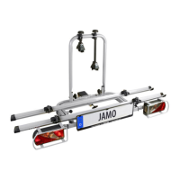
Towbar conditions for the cycle rack JAMO
The cycle rack can be mounted onto all towbar balls under the following conditions.
The maximum useful load of the cycle rack is: 50 kg Test the suitability of the
towbar.
The towbar type must have been officially approved.
The ball and towbar itself need to be cast as one part.
The towbar material must have a minimum quality of St 52-3.
Note: Usually the towbars are made of St 52-3. Cast material such as e.g. GGG 40 is not
suitable (only suitable from GGG 52 upwards). Not suitable for aluminium towbars. The
following towbars are currently made of GGG 40: If in doubt ask the manufacturer of the
towbar.
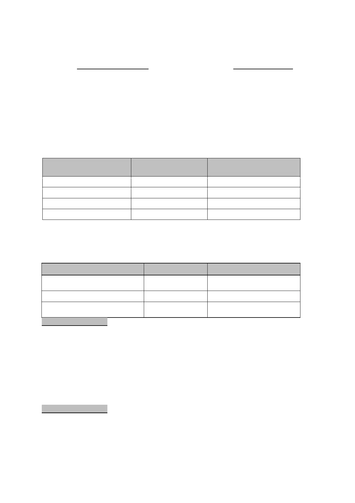
Manufacturer of the towbar
Suitable for vehicle type
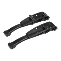
Assembly picture 1
All screws should be treated with oil or grease to ensure long-term easy movement. First,
screw the base to the pre-assembled carrier table. Fold the swing frame downwards by
first unlocking the securing mechanism at the side. The plate with the receptacle for the
securing bolt as well as both rests for the swing frame (see photo) must be placed up
against the outer carrier table and screw the base into place using the M8 x 50 screws, 8
mm washers and M8 nuts. The screw heads should all go from inside to out. Before
tightening the screws up, fold the swing frame back and secure using the two securing
bolts. Now screw the M16 x 130 screw approximately 1 cm into the base. Then check to
make sure that both securing bolts can be shot home.
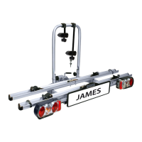
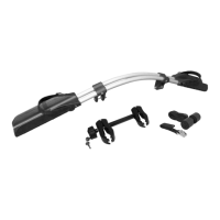
Assembly picture 2
Place the U – bracket onto the designated tube sleeves and secure with 2 lock screws,
(M8 x 60) washers (8 mm) and knurled nuts (M8). Insert the pre-assembled lamp holders
with the 13-wire plug into the end of the tube of the swivel frame. Ensure that the lamp
holder with the reverse light is on the right (see photo). The lamp holders have two setting
options. For vehicles that are wider than 1740 mm (see section 13 in the car documents),
the lamp holders need to be mounted in the outer position (see photo). For vehicles that
are less wide than 1740 mm, the inner hole distance needs to be selected. Align the lamp
 Loading...