This document describes the rZ cPIAEC 6 and cPIAEC 8 2 pipes heat exchanger, an installation manual for the ceiling version.
Function Description
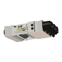
The rZ cPIAEC 6 and cPIAEC 8 are heat exchanger units designed for ceiling installation, providing heating and/or cooling functionalities. These units are part of a modular system, allowing for various configurations and adaptations to different installation requirements. They are equipped with a hydraulic network for water circulation, an air plenum for air distribution, and a fan unit for air movement. The system is designed to be integrated into a non-corrosive, non-marine, non-acidic, non-alkaline, dust-free, and without any inflammable gases environment.
The units utilize a 2-pipe system, meaning they can provide either heating or cooling, but not simultaneously. The air blowing temperature must not exceed 60°C, and the relative humidity in order to prevent excessive condensation of the device should be between 27°C (dry bulb) and 65%. The hydraulic components are designed for the composition of the water of the network, its treatment, and the frequency of maintenance provided to the hydraulic system. The system includes electrical parts and hydraulic components, which are critical for safe and adequate operation.
The cPIAEC plant is equipped with Ø200mm pre-cutters designed specifically for the clipping of the AIRCLIP plastic air ducts. These pre-cutters facilitate the connection of air ducts for efficient air distribution. The return air plenum allows for multiple pre-cuts (3 for cPIAEC 6 and 4 for cPIAEC 8) to accommodate various ducting configurations.
Important Technical Specifications
- Models: rZ cPIAEC 6 and rZ cPIAEC 8.
- Pipes: 2-pipe system.
- Air Ducts: Ø200mm pre-cutters for AIRCLIP plastic air ducts.
- Water Quality: According to VDI2035 rule.
- Maximum Glycol Content: 20%.
- Minimum Temperature: 5°C.
- Maximum Temperature: 70°C.
- Maximum Operating Pressure: 10bar PN16.
- Power Supply: 230V +/- 10%, 50-60 Hz.
- Power Consumption (Service): 2.5 W.
- Absorbed Power (Start-up): 36 W.
- Inrush Current: 100 mA.
- Spring Tension: 125 N.
- Pressure Loss Coefficient (Kv): 0.5.
- Flow Rate (q): m³/s.
- Section (S): m².
- Automatic Balancing Valves: CuZn39 Pb2 hot-forged brass pressure points and plugs, stainless steel spring. Upstream and downstream pressure measurement sockets for Δp control. Adjustment accuracy +/- 10% constant over the entire flow range. Operating range for cartridges: Green (17 to 200 kPa, DN 15-20 white cursor) and Red (30 to 400 kPa, DN 15-20 grey cursor).
- Ultrasonic Sensor for Energy Metering: Nominal flow 1,5m3/h, Maximum pressure 16 bar, Minimal flow 15l/h, Temperature range 0/90°C, In/out ΔT° range 2/90°C. Straight lengths recommended before the sensor: 110mm.
- Electrical Protection: Minimum cable cross section is 1.5 mm². Line feeding the cPIAEC must have a differential device of 30mA.
- EC Centrifugal Fan: Ball bearings, 230V~ 50/60Hz, Class F winding, IP44 protected. Temperature range from -20°C to +50°C. 146mm diameters turbine, double inlet.
- Safety Thermostat: Automatic reset, 80-86°C range.
- Dimensions (cPIAEC 6): Thickness 184mm, Width 666mm, Length 239mm. Weight (with blow outlet plenum) 24kg. Weight (with all accessories) 3kg. Number of blowing outlets 3 x Ø200.
- Dimensions (cPIAEC 8): Thickness 239mm, Width 911mm, Length 239mm. Weight (with blow outlet plenum) 33kg. Weight (with all accessories) 4kg. Number of blowing outlets 4 x Ø200.
- Maximum Power Input (cPIAEC 6): 140 W.
- Maximum Power Input (cPIAEC 8): 280 W.
- Electrical Capacity (cPIAEC 6): 1500(2 x 750) W.
- Electrical Capacity (cPIAEC 8): 2500(2 x 1250) W.
Usage Features
- Installation: The unit must be installed on a clean and ventilated environment. It is designed to be suspended from the ceiling. The installation, commissioning, and maintenance of all EUREVIA heating and/or cooling systems must be carried out by qualified persons having been specifically trained on these products.
- Air Distribution: The system allows for flexible air distribution through various ducting options. Outlets and shutters on the supply and/or return air plenum can be configured for air duct connections. Hydraulic outfits and controller inside the device are also part of the setup.
- Condensate Recovery: An internal tray with a 13.5 mm outside diameter drain is included for condensate recovery. The connecting hose should be 12/14 evacuation PVC tube.
- Hydraulic Battery: Equipped with a ½” connector for cPIAEC 6 and a ¾” on the cPIAEC 8, all with female thread. The water inlet of the battery is located from the bottom and the exit is made from the top. The hydraulic battery has a trap located at the top just above the water outlet.
- Automatic Balancing: The system incorporates automatic balancing valves to ensure optimal flow and pressure within the hydraulic network.
- Damper Installation: A damper can be installed in the damper to regulate airflow. This involves installing the damper into the hole of the bracket and blocking it with the rubber washer.
- Air Filter: Galvanized steel frame with pleated polyester fiber filter. Resistance to temperatures up to 80°C. Efficiency class EN 779: G4 or F5.
- Control: The cPIAEC control unit manages the system. In case of malfunctions, refer to the control points listed in the troubleshooting section.
Maintenance Features
- General Precautions: Regular and proper maintenance is required throughout the heating and/or cooling whole system in order to avoid any problem of clogging and corrosion. EUREVIA guarantees do not cover damages caused by limestone and corrosion.
- Power Supply: Any electrical device must be installed by an authorized person in accordance with the standards and regulations in force.
- Damper Maintenance: Periodically check the damper for proper functioning.
- Air Filter Maintenance: The filter should be regularly checked and replaced.
- Hydraulic Connections: Regular checks for leaks and proper functioning of valves and fittings.
- Condensates Recovery: Ensure the condensate tray and drain tube are clean and free from blockages.
- Electrical Protection: Verify the integrity of electrical connections and protective devices.
- EC Centrifugal Fan: Regular inspection of the fan for cleanliness and proper operation.
- Safety Thermostat: Check the thermostat for correct temperature settings and functionality.
- Troubleshooting: The manual provides a comprehensive troubleshooting guide with possible causes and corrective actions for various issues such as the unit not working at all, cooling or heating performance limitations, clogged filter, air leak on the network, undersized system, presence of air on the hydraulic network, vibration, presence of an obstacle, and insulation problems.
- Care & Maintenance Schedule:
- Fans: Check cleanliness, check turbines or rotating parts (visually), check all fixings (visually), corrosion control, check ball bearings (noise), and check connections.
- Filtration: Check regularly the filter soiling, verification of the tightness of the assembly, replacement, and checking the property.
- Battery: Check the level of frost protection and battery purge.
- Removal of the Power Supply Cable: Remove the quick connector, remove the front panel cover, unscrew the two ¼ turn screws, remove the two visible tabs above the connector, lift the insulating foam, and remove the female connector.
- Removal of the Master Cable: Remove the fast connector (s) (4 wires) from the motor connecting the regulator, remove the 4 wires (orange, yellow, white, gray) using a screwdriver, and remove the connector.
- Removal of the Fixing Frame: Remove the 2 hexagon bolts located on the fan support metal frame and remove the 4 hexagon screws located on both sides of the frame.
- Filter Replacement: Pull the filter on the top in order to tilt it and then remove it. To install the new filter, refer to the direction of the airflow using the arrow located on the edge of the frame.
- Replacement of the Shutter Thermal Actuator: Switch off the power supply of the fancoil, unclip the shutter cover using a screwdriver, remove carefully the thermal actuator to be changed, insert the new thermal actuator, and replace the shutter cover.
- Replacement of the Electric Resistances: Remove the black circular covers, disconnect the resistances power supply from the regulator, disconnect the connections to the safety thermostat, remove the resistances, and proceed in reverse order to put new resistances.