EasyManua.ls Logo

Euroheat Harmony 5 User Manual

Euroheat Harmony 5
28 pages
To Next Page IconTo Next Page
Page #1 background imageLoading...
Page #1 background image
1
© Euroheat Distributors (H.B.S) Ltd. Dec 2004
E & OE Installation Servicing IN1045 Ed C
Installation & Servicing
Harmony 5
&
Stanford 50
Gas Balanced Flue Stove
Serial Number
Part No.
Euroheat Distributors
(H.B.S.) Ltd.,
Unit 2, Court Farm
Business Park,
Bishops Frome,
Worcestershire,
WR6 5AY.
E
F
E
L

Other manuals for Euroheat Harmony 5

Question and Answer IconNeed help?

Do you have a question about the Euroheat Harmony 5 and is the answer not in the manual?

Euroheat Harmony 5 Specifications

General IconGeneral
CategoryStove
ModelHarmony 5
Nominal Heat Output5kW
Flue Outlet Diameter125mm
Fuel TypeWood
Flue Diameter125 mm
Flue Outlet LocationTop

Summary

Safety Precautions

Manufactures Identification Plate

Location and method to access the appliance's identification plate.

Euroheat Appliance Serial Number

Lists the five locations where the appliance serial number can be found.

Technical Data with Eurosit Gas Valve 630

Technical Data with Mertik Maxitrol GV34 Gas Valve

Primary Air Collar Adjustment

Appliance Location Guidelines

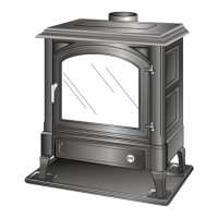
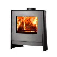
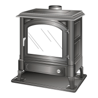
Requirements for stove placement, hearth, and surrounding clearances.

Hearth and Fireplace Requirements

Balanced Flue Kit Components

Standard Top to Horizontal Flue Kit (MS91032)

Details the parts included in the standard horizontal balanced flue kit.

Standard Top to Vertical Flue Kit (MS91060)

Details the parts included in the standard vertical balanced flue kit.

Balanced Flue Additional Accessories

Calculating Flue Aspect Ratios

Example Horizontal to Vertical Ratio Calculations

Vertical to Horizontal Ratio Graphs

Example Flue Calculation

Fitting the Flue Kit

Flue Terminal and Material Safety

Position of Flue Terminal on Outside Wall

Specifies the correct positioning for an external wall flue terminal.

Flueing Through Combustible Material

Instructions for safely routing the flue through combustible wall sections.

Balanced Flue Terminal Position Requirements

Location of Flue Outlets from Appliances

Minimum separation distances for flue terminals based on location.

Gas Supply Installation and Appliance Location

Gas Supply Installation Requirements

Standards and procedures for installing the gas supply line.

Appliance Location Requirements

Guidelines for stove placement, hearth, and surrounding clearances.

Gas Connection Procedure

Fitting the Coal Effect Kit

Gas Control Valve Operation

Eurosit Gas Valve 630 Controls

Explains manual and thermostatic control of the Eurosit valve.

Lighting the Appliance

Step-by-step instructions for igniting the pilot and main burner.

Thermostatic Eurosit Gas Valve 630 Details

Mertik Maxitrol GV34 Gas Valve Operation

Lighting the Mertik Maxitrol Valve

Instructions for igniting the pilot and main burner with the Mertik valve.

Manual Control of Mertik Maxitrol Valve

How to adjust heat output using the manual control knob.

Mertik Maxitrol GV34 Gas Valve Adjustments

Gas Valve Cover and Adjustment Screws

Details on removing the valve cover and adjusting pressure settings.

Gas System Connections and Controls

Gas Pressure Test Nipple Locations

Identifies the locations of test nipples for gas pressure measurement.

Fitting the Remote Control Components

Instructions for connecting remote control motor and micro switch.

Fitting Electrical Connections

Guide for connecting the wiring loom to receiver and motor.

Receiver Unit Location

Specifies the correct placement for the remote control receiver.

Installer Advice for Users

Gas Burner and Jet Maintenance

Removing the Gas Burner

Steps for lifting and removing the main gas burner assembly.

Removing the Main Burner Jet

Procedure for replacing the main burner jet after burner removal.

Pilot Jet Replacement Procedure

Service Record Template

Related product manuals