Pay special attention that the figures in table are only rough values and in some cases
may not agree with real ones.
Such situation can appear in e.g. vehicles fitted with semi-sequential or full group (all
injectors activated simultaneously) injection. In such vehicles nozzle diameters will be smaller than
these given in the table due to the fact that in such type of LPG supply control the volume of
supplied LPG is greater than for full sequence – twice for the semi-sequential and four times for full
group injectors.
2. Description of the VECTOR diagnostic program
2.1. Connection of the controller to a PC
If the controller is connected correctly, connect VECTOR to a PC with installed VECTOR
diagnostic program with help of an interface VECTOR. Before starting the program turn the
ignition (supply the controller with voltage); this is necessary because after ca. 10 minutes without
power supply from the ignition switch the controller goes to the sleep mode, where the
communication is impossible. After start of the program – if the serial port COM is selected
properly – the controller should establish connection with the diagnostic program, what is signalled
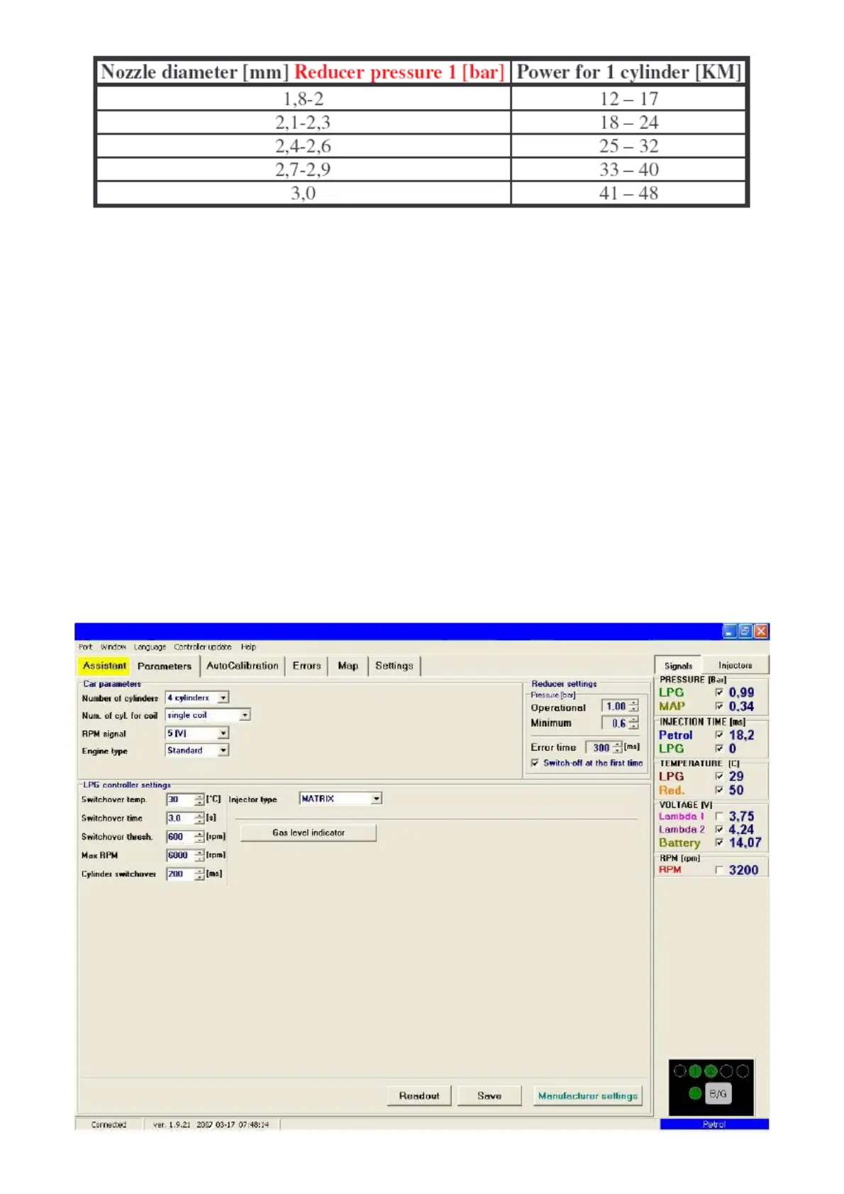
with the message “Connected” in the left lower corner of the program window. The Parameters
window is shown at the Fig. 4.
Fig. 4 Parameters window