2.4. Signals, injectors, switchboard
On the right side of the window (Fig. 4) there is the window Signals and the window
Injectors. The window Signals contains following signals measured by the controller:
• LPG pressure [bar] – LPG pressure value (pressure difference between the pressure
regulator and the suction collector)
• Pressure MAP [bar] – pressure value within the suction collector (the absolute pressure
value)
• Injection time gasoline [ms] – injection time for gasoline (for the first injector)
• Injection time LPG [ms] – injection time for LPG (for the first injector)
• LPG temperature [°C] – LPG temperature at the pressure regulator output
• Pressure regulator temperature [°C] – temperature of the fluid within the pressure regulator
• Lambda 1 voltage [V] – voltage at the lambda 1 probe
• Lambda 2 voltage [V] – voltage at the lambda 2 probe
• Power supply voltage [V] – voltage at the controller’s power supply
• RPM [rev/min] – engine revolutions
All described signals are visible also on the oscilloscope. It is possible to switch out given
signal so that it is not visible on the oscilloscope. For this purpose click on the signal’s value to
mark it; when marked, the signal’s colour can be changed.
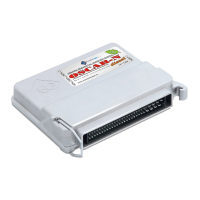
To enter the Injectors window press the puss button Injectors.
Fig. 5 The Injectors window.
The window shows times of gasoline injection for individual injectors. Below are
shown active LPG injectors. This option is designed for switching out individual
LPG injectors. For example, in a 4-cylinder engine usually 4 LPG injectors are
active (green colour). To switch out given injector click on its image, what causes
switching out of this injector and switching on the adequate gasoline injector. This
option makes possible diagnostic of mechanical damage of an injector. When the
voltage at the ignition switch is off all LPG injectors become on.
Below the Signals and Injectors windows there is the LED switchboard.
Fig. 6 The LED switchboard
In the switchboard is situated the switch for change of fuel type. The LED
nearby the switch informs about controller’s working mode:
• Off – gasoline
• On – LPG
• Blinks – automatic mode
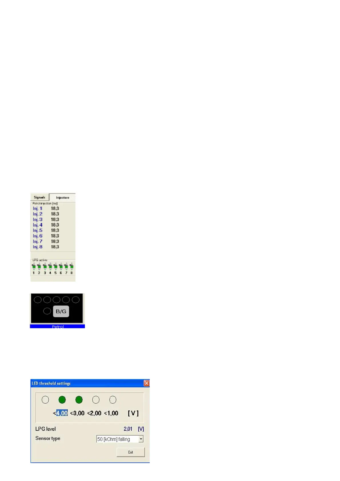
Under the switchboard is shown the present fuel type. In the top of the switchboard there are 5
LEDs informing about the LPG level in the tank. By clicking one of four LEDs we enter the LED
threshold setting window.
Fig. 7 LED threshold setting
In this window we can set voltage causing switching on
of individual LEDs. We select also the LPG level sensor
type.The LPG level voltage is also displayed.
 Loading...