EasyManua.ls Logo

EUROSTER 11 - User Manual

EUROSTER 11
4 pages
Print Icon
To Next Page IconTo Next Page
Loading...
EUROSTER 11, 11C USER MANUAL 1
EUROSTER 11/11C
CENTRAL HEATING PUMP CONTROLLER
MANUFACTURER: P.H.P.U. AS, Polanka 8a/3, 61-131 Poznań, POLAND
1. INTRODUCTION
Carefully study this user manual to learn how to correctly operate the EUROSTER 11/11C
central heating (CH) pump controller.
2. FIELD OF APPLICATION
EUROSTER 11/11C is an electronic controller used to automatically turn ON/OFF CH system
circulation pump depending on CH system water temperature. The pump may circulate water
through a system heated by a coal- or gas-fired boiler. Water temperature is sensed by a
sensor located at the CH system inlet.
The controller will also turn the pump OFF as soon as coal-fired boiler flame is put out. Water
should not be circulated unless it is heated by the boiler since chimney air draft cools down the
boiler water much faster than the radiator water.
Controller is equipped with a knob used to preset optimum CH system water temperature
(most often around 40ºC). If the controller cooperates with a gas-fired boiler, its set
point MUST BE LOWER than the boiler thermostat set point. Set the controller set
point higher than the dew point in order to prevent boiler sweat during the process
of heating the water up.
The EUROSTER 11/11C controller features the ANTY STOP
function that prevents idle pump rotors and valves against
seizing. Once the heating season is over, every 14 days the
function automatically turns ON the pumps and the valves for
30 seconds. To that end the controller must be left powered up.
3. VISIBLE CONTROLLER ELEMENTS
1. Mains switch
2. 230 VAC~ mains input
3. 230 VAC~ power supply to pump
4. Input for the boiler temperature sensor
cable
5. Temperature preset knob
6. Controller turned on green LED
7. Pump turned on red LED
8. Continuous operation switch
Question and Answer IconNeed help?

Do you have a question about the EUROSTER 11 and is the answer not in the manual?

Summary

Introduction

Field of Application

Visible Controller Elements

Installation

Mount the Controller

Mount the controller box on a wall or supporting structure using supplied fasteners.

Install Temperature Sensor

Install the CH system inlet temperature sensor at the boiler outlet pipe, close to the boiler.

Hook Up Pump Power Supply Cable

Connect the PE, N, and L wires to the appropriate terminals for pump power supply.

Verify Connections

Check all cable connections and ensure terminal box lids are tightened.

Hook Up the Controller

Plug the controller power supply cable into a grounded 230V/50Hz mains socket.

Turning the Controller On

Automatic Operation

Manual Operation

Troubleshooting

Device is Dead

Troubleshoot a dead device where the green LED does not illuminate.

Pump Does Not Operate

Troubleshoot when the pump does not operate despite the red LED being ON.

Pump Continuously Engaged

Troubleshoot a pump that remains continuously engaged.

Compatibility and Specifications

Compatibility with Standards

Details compliance with EMC and LVD EU Directives.

Specifications

Lists technical details like mains voltage, output load, hysteresis, and dimensions.

Kit Contents

Connection Diagrams

Guarantee and Waste Management

Electronic Waste Management

Information on proper disposal of electronic waste and packaging.

Guarantee Certificate

Details warranty terms, conditions, and information for claims.

Overview

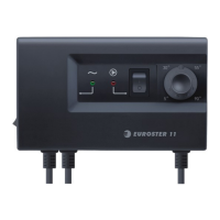
The EUROSTER 11/11C is an electronic controller designed for central heating (CH) systems, specifically to manage the operation of a circulation pump. It automatically turns the CH system circulation pump ON or OFF based on the water temperature in the CH system. This device is suitable for systems heated by either coal-fired or gas-fired boilers. The water temperature is monitored by a sensor strategically placed at the CH system inlet.

Function Description:

The primary function of the EUROSTER 11/11C is to optimize the operation of the CH pump. When the CH system water temperature rises above a user-defined set point, the controller activates the pump to circulate the heated water. Conversely, when the temperature drops below the set point, the pump is turned off. This intelligent control prevents unnecessary circulation of unheated water, which can lead to energy waste and faster cooling of the boiler water, especially in coal-fired systems where chimney air draft can accelerate heat loss.

A key feature for coal-fired boilers is the controller's ability to turn the pump OFF as soon as the boiler flame is extinguished. This prevents the circulation of unheated water, which would otherwise cool down the boiler more rapidly than the radiator water.

The controller is equipped with a knob for presetting the optimum CH system water temperature, typically around 40°C. For systems with gas-fired boilers, it is crucial to set the controller's set point lower than the boiler thermostat's set point. Additionally, the controller's set point should be set higher than the dew point to prevent boiler "sweat" (condensation) during the heating process.

The EUROSTER 11/11C also incorporates an "ANTY STOP" function. This preventative measure is designed to protect idle pump rotors and valves from seizing due to prolonged inactivity. After the heating season concludes, this function automatically activates the pumps and valves for 30 seconds every 14 days. For this feature to work, the controller must remain powered up.

Usage Features:

The controller offers both automatic and manual operation modes.

  • Automatic Operation: In this mode, the controller continuously monitors the sensor temperature and compares it to the knob-preset set point. The CH system circulation pump is engaged when the sensor temperature exceeds the set point and disengaged when it falls below the set point.
  • Manual Operation: This mode is useful for specific tasks such as de-aerating the system or in the event of a temperature sensor failure. To activate manual operation, the continuous operation switch (labeled 8 in the diagram) is turned to the "I" position, which illuminates the red LED (7) and engages the pump regardless of the actual sensor temperature.

Installation Procedure:

Installation of the EUROSTER 11/11C requires careful attention to safety and should only be performed by qualified technicians due to the presence of hazardous voltages.

  1. Mounting: The controller box is mounted on a wall or suitable supporting structure using the supplied nylon nail-it fasteners (anchors). Controller cables should also be secured to the wall using fasteners.
  2. Temperature Sensor Installation: The temperature sensor should not be immersed in liquids or installed within a stream of flue gases. It must be installed at the boiler point specifically designed for it or on an unshielded boiler outlet pipe, as close to the boiler as possible. Hose clips are used to tighten the sensor to the pipe.
  3. Pump Power Supply Cable Hook-up: The yellow (or yellow-green) PE wire connects to the earth terminal, the blue wire to the N terminal, and the brown wire to the L terminal.
  4. Connection Verification: All cable connections must be checked and terminal box lids tightened.
  5. Controller Hook-up: Ensure controller cables are protected against incidental cuts. The controller's power supply cable is then plugged into a 230V/50Hz mains socket equipped with a grounding pin.

Important Installation Note: The controller must not be installed in locations where the ambient temperature exceeds 40°C.

Turning the Controller ON:

  1. Turn the controller mains switch (1) to the "I" position.
  2. The green LED (6) will illuminate, indicating the controller is powered on.
  3. For the E11C model, the ANTY STOP function will activate the pump for approximately 30 seconds (red LED 7 will illuminate).
  4. Use the knob (5) to set the desired temperature.

Maintenance Features:

  • ANTY STOP Function: As described, this automatic function helps prevent pump and valve seizing by periodically activating them, extending their lifespan and reducing maintenance needs.
  • Troubleshooting: The manual provides guidance for common issues:
    • Device is dead (green LED off): Suggests a burnt mains fuse or ROM failure. Requires fuse replacement or professional servicing.
    • Pump does not operate: Recommends using the manual operation switch to check if the pump turns on. If the red LED (7) illuminates but the pump doesn't work, check if the pump operates when connected directly to a mains socket. If so, the controller needs servicing. If the red LED doesn't illuminate, the controller needs servicing.
    • Pump continuously engaged: Advises checking if the manual operation switch (8) is turned OFF. If the red LED (7) is still ON when the knob is turned to maximum temperature, the controller needs servicing. If the LED goes OFF but the pump doesn't stop, check the connections.

Important Technical Specifications:

  • Mains: 230 V 50Hz
  • Output rated load: 3 A
  • Hysteresis: 5°C
  • Length of cables: 1.5 m
  • Dimensions (width x height x depth): 150 x 90 x 52 mm

Kit Contents:

  • Controller box with temperature sensor
  • Sensor hose clip
  • Box fasteners/anchors
  • Installation & Operation Manual
  • Template to drill holes for fasteners/anchors

Compliance:

The EUROSTER 11/11C controller complies with all requirements of the EMC and LVD EU Directives. The CE Conformity Declaration is available on the manufacturer's website.

Electronic Waste Management:

The manufacturer encourages responsible disposal of the device at an electronic waste management facility when it no longer meets requirements. Electronic waste is collected free of charge by local distributors. Inappropriate disposal can lead to environmental pollution. Cardboard packaging should be disposed of at a paper recycling facility.

Warranty:

The device comes with a 24-month warranty from the sale date. Claims require the controller and warranty certificate to be supplied to the seller and are processed within 14 business days. Repairs must be performed by the manufacturer or authorized parties. The warranty is invalidated by mechanical damage, incorrect operation, or unauthorized repairs.

EUROSTER 11 Specifications

General IconGeneral
BrandEUROSTER
Model11
CategoryController
LanguageEnglish

Related product manuals