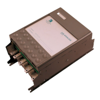
Do you have a question about the Eurotherm 590A SERIES and is the answer not in the manual?
General advice for secure mounting and environmental suitability of the product.
User responsibility for system integration, applicability, and safety.
Identifies potential motor speed and direction issues under fault conditions.
Compares the 545 Series product with the new 590A for application convenience.
Provides a detailed terminal mapping for converting from 545 to 590A.
Introduces the 590A series of motor speed controllers and their capabilities.
Outlines general specifications for the drive's control and power circuits.
Details control circuit specifications including enclosure, isolation, and protection features.
Specifies power circuit details like configuration, mains supply, voltage ranges, and current ratings.
Lists output current and power ratings across different models and operating conditions.
Details armature current ratings, maximum ambient temperature, and overload capacity.
Specifies the output current ratings for the motor field excitation.
Provides dimensions, weight, airflow clearance, and termination details for mounting.
Explains the numerical order code used to specify the 590A/591A three-phase converters.
Guides on mounting the controllers onto a flat surface and relevant fixing considerations.
Details requirements for heat dissipation and air flow for optimal operation.
Provides essential wiring instructions for basic speed control configuration.
Offers additional wiring notes regarding indicators, isolation, and testing procedures.
Outlines specific installation requirements for compliance with UL 508 standards.
Details the function and connection of each terminal on the control board.
Explains the function and connection of each terminal on the power board.
Introduces guidelines for maximizing Electro Magnetic Compatibility (EMC) in the operating environment.
Discusses EMC filter impact on earth-fault systems and necessary safety precautions.
Provides methods to reduce radiated emissions and comply with EMC standards.
Details requirements for proper screening and earthing within an enclosure for EMC compliance.
Describes the power supply path, protection, and field excitation circuits.
Explains the isolation, synchronisation, and control operational principles of the drive.
Details the logic for starting, stopping, and fault handling of the drive.
Describes the function and initial settings of the preset potentiometers for system tuning.
Explains the functionality of user-selectable option switches S8 and S9 for configuration.
Details the procedure for calibrating speed, armature current, and field voltage.
Guides on selecting tach feedback source and adjusting for full speed voltage.
Outlines steps to calibrate armature current based on motor nameplate ratings.
Explains how to set field voltage using option switches and preset P11.
Lists critical checks to perform on supply voltages, ratings, and wiring before powering up.
Describes essential preparation steps, including isolating power and disconnecting the load.
Provides step-by-step instructions for verifying connections, voltages, and initial drive operation.
Guides on tuning control loop parameters for stable and responsive motor performance.
Introduces the type 5570 Diagnostic Test Unit and its features for signal monitoring.
Outlines the recommended procedure for using the Diagnostic Test Unit to identify fault conditions.
Details the correct procedure for connecting and disconnecting the diagnostic test unit.
Explains the function of each LED indicator on the main control board for status monitoring.
Provides charts to interpret LED status combinations for stop and start conditions.
Correlates LED states with specific stop conditions and required checks.
Correlates LED states with specific start conditions and necessary troubleshooting steps.
Lists test points, conditions, and expected voltage measurements for the diagnostic unit.
Describes the new 590 Power Board and its key differences from previous versions.
Details the power supply generation and fan connection requirements for the new board.
Explains how thyristor stack synchronisation and phase rotation signals are generated.
Specifies the fuse protection for auxiliary circuits and the power supply.
Explains how armature current feedback is achieved for closed-loop control.
Details the connection of the power contactor and its control relay for sequencing.
Describes how to connect an external AC supply for motor field excitation.
Mentions new trigger plugs for thyristor gate/cathode connections.
Introduces CEMEP and its role in standardizing EMC compliance for European drives.
Explains the application of the EMC Directive and Eurotherm's adherence to CEMEP recommendations.
Clarifies responsibility for CE marking and EMC compliance for components and final apparatus.
Discusses relevant EMC emission and immunity standards for different operating environments.
Details the selection of EMC filters and line chokes for compliance with EMC standards.
Lists EMC emission and immunity performance criteria when using specified filters and chokes.
Defines the responsibilities for EMC conformity and CE marking for apparatus incorporating the drive.
Provides information on specifying spare parts and kits using alpha-numeric codes.
Outlines a regular maintenance program for ensuring reliable operation of the equipment.
Lists Eurotherm Drives' customer support services including sales, technical, and repairs.
Provides guidance on the proper disposal of product materials according to waste regulations.
Mentions that transport packaging is environmentally compatible and suitable for central disposal.
 Loading...