Do you have a question about the Eurotherm 605 Series and is the answer not in the manual?
Overview of the 605 Series Frequency Inverter and its capabilities.
Details of optional accessories and their part numbers for the inverter.
Guidance on planning installation, operation, and programming for the inverter.
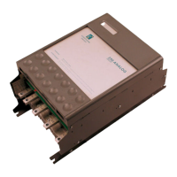
Identifies and labels the main physical parts of the 605 Series Inverter unit.
Lists and describes the general control features available for the inverter.
Explains the structure and meaning of each block in the inverter's product code.
Describes the main functional blocks: Filter, Power, and Control Boards.
Details requirements for mounting the inverter, including dimensions and fixings.
Specifies necessary air clearances for ventilation for cubicle and wall-mounted installations.
Covers electrical installation aspects, including wiring precautions.
Step-by-step instructions for connecting power and motor cables.
Instructions for connecting control cables, including EMC requirements.
Describes the fitting procedure for optional accessories like the remote Operator Station.
Essential checks before energizing the inverter and system for safety and correct setup.
Explains the different modes of controlling the inverter: Remote vs. Local.
Guides on selecting between Local and Remote control modes using the Operator Station.
Outlines initial startup procedures for remote control using terminal connections.
Details the startup routine when using the Operator Station for local control.
Guides on setting up the inverter using Sensorless Vector Fluxing or Open-loop V/F fluxing modes.
Provides methods for manual tuning using motor equivalent circuit or a simple sequence.
Explains normal and advanced stopping methods like Ramp to Stop, Coast to Stop, and Forced Stop.
Explains how to connect the Operator Station for local control, monitoring, and programming.
Provides information on personalizing the Operator Station for specific applications.
Lists diagnostic parameters accessible via the MMI, including speed, current, and trip status.
Details the control keys for operating the inverter locally and for programming.
Describes the menu structure with 5 levels and selectable viewing levels.
Explains how to activate password protection to prevent unauthorized parameter modification.
Explains how macros are used as starting points for application-specific programming.
Introduces block diagram programming as a visual method for planning inverter software.
Lists all available function blocks with corresponding page numbers for detailed descriptions.
Details the analog input block, converting voltage or current inputs to a configurable percentage range.
Explains how the digital input block converts physical input voltage to TRUE or FALSE control signals.
Explains how the PID function block is used for process control, trimming setpoint based on feedback.
Explains parameters related to the sequencing (start and stop) of the inverter.
Explains what happens when a trip occurs, inverter indications, and operator station notifications.
Lists common trip messages and their possible causes for troubleshooting.
Provides a table of common problems, causes, and remedies for troubleshooting.
Recommends periodic inspection for dust and obstructions affecting ventilation.
Advises on keeping a backup of application data on the Operator Station.
Provides information required when returning the unit for service.
Explains that the inverter's reaction to commands is defined by a state machine.
Describes how state transitions occur based on specific causes, illustrated by a transition matrix.
Provides a comprehensive list of all parameters, their tag numbers, blocks, types, and ranges.
Lists default parameter values varying by language, supply voltage, and power rating.
Details operating temperatures, altitude, humidity, atmosphere, and climatic conditions.
Outlines EMC compliance requirements based on installation and filter usage.
Provides guidelines for cable types, segregation, length, and screen termination for EMC compliance.
Lists control terminals, their names, ranges, default functions, and descriptions.
Outlines EMC compliance requirements, including minimizing radiated emissions and earthing.
Explains EMC installation options for Class A and Class B operation, including screening and earthing.
Covers UL compliance requirements for motor overload, short-circuit protection, and branch circuit protection.
Provides information on EMC and Low Voltage Directive (LVD) CE marking requirements.
Discusses applying inverters for speed control of synchronous motors.
Explains the use of brake motors and how inverters control them.
Explains how dynamic braking dissipates energy to prevent DC link overvoltage.
Guides on calculating braking requirements and selecting appropriate brake resistors.
Describes connecting to the inverter's P3 port for parameter monitoring and updating via PC.
Details the pinout and signal assignments for the P3 port connector.
Introduces the supplied macros and identifies Macro 1 as the factory default.
Details the default macro providing basic speed control, including terminal assignments.
Describes Macro 2 for speed control with Run Forward/Run Reverse functionality.
Details Macro 3 for speed control with raise/lower trim interface.
Explains Macro 4 for PID process control using analog inputs and digital inputs.
Describes Macro 5 for speed control using preset speeds selected by digital inputs.
Details Macro 6 for closed-loop speed feedback using encoder inputs and PID control.