Do you have a question about the Eurotherm 590+ Series and is the answer not in the manual?
Check for transit damage, verify product code, and store unit in a well-ventilated place away from hazards.
Save packaging for returns; improper packaging can cause transit damage. Use safe lifting procedures.
Manual is for installer, user, and programmer. Read safety information before installation and operation.
Plan installation requirements including certification, local codes, and supply/cabling.
Converter controls DC motor using inner Current Loop and outer Speed Loop, selectable via Operator Station.
Details control circuits, output control, control action, speed control, range, accuracy, adjustments, protection, and diagnostics.
Explains the alphanumeric code identifying calibration, factory settings, and country of origin.
Identifies the unit using an alphanumeric code for calibration and settings, specific to North America.
Details product code for door assembly, including livery, mechanical style, operator station, and language.
Illustrates different frames and output current ratings for 590+ and 591+ series.
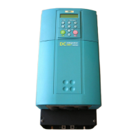
Identifies components for 590+ Controller (Frames 1 & 2) with a diagram.
Covers unpacking, lifting, changing output terminals, removing covers, product dimensions, and mounting the converter.
Details electrical installation requirements, including cabling, glands, protective earth, power wiring, auxiliary supply, field, armature, and external AC field connections.
Outlines minimum connections for general-purpose operation, important connections, protective earth, power wiring, and control wiring.
Details minimum connections for Frame H, including protective earth, power wiring, auxiliary supply, field, armature, and external AC field.
Explains internal/external supply options and provides connection diagrams for Frame 2 and Frame 3 power boards.
Details external connections for Frame H, including motor field, power control, and armature voltage sense.
Covers fitting the remote 6901 Operator Station, speed feedback, and communications technology options.
Provides guidance on installing external AC supply EMC filters, including cubicle mounting and connection details.
Discusses the use of circuit breakers and potential issues with earth leakage currents and EMC filters.
Provides detailed dimensional drawings for converter installation across various frames (1, 2, 3, 4, 5, H).
Essential checks before applying power, ensuring safety, and preparing to energize the converter and system.
Explains the four ways to control the converter using Remote and Local modes for Start/Stop and Speed Control.
Details how to select local or remote control modes using the L/R key and Operator Station LEDs.
Explains the meaning of the HEALTH and RUN LEDs for indicating converter state (e.g., Stopped, Running, Tripped).
Guides through initial start-up routines, including preliminaries and calibration of analog tacho option boards.
Covers calibration steps for Microtach/Encoder feedback, including setting drive/motor ratings and field control parameters.
Step-by-step guide for initial start-up, covering setpoint inputs, current clamp settings, speed feedback, and parameter saving.
Details stopping methods like Normal Stop, Program Stop, and Coast Stop, explaining their parameters and behavior.
Explains how to achieve a normal stop by removing 24V from Terminal C3, defining motor speed and stopping rate.
Describes Program Stop achieved by removing 24V from Terminal B8, detailing PROG. STOP TIME and PROG. STOP I LIMIT.
Details connecting the Operator Station as a plug-in MMI for local control, monitoring, and programming.
Explains the two operating modes: Remote Control Mode and Local Control Mode.
Defines keys for programming the converter (navigation, parameter editing) and for local operation (motor control).
Describes Operator Station LEDs (HEALTH, LOCAL, RUN, STOP, FWD, REV) and their meanings for converter state.
Explains the menu structure, main menus (Diagnostics, Setup, Password, etc.), and selectable viewing levels.
Covers quick tag information and procedures for changing stack size (3-button reset) and resetting to factory defaults (2-button reset).
Allows selection between full or reduced menu systems for easier navigation of the MMI.
Explains how to select the display language, with ENGLISH as default and others available.
Details how to activate and deactivate password protection to prevent unauthorized parameter modification.
Guides on saving application data, restoring saved settings, and copying applications via host computer connection.
Explains using MMI or ConfigEd Lite for block programming, including function blocks and software links.
Details Configuration and Parameterisation Modes, and how to make/break links in Configuration Mode.
Outlines rules for programming in Parameterisation and Configuration modes, and saving modifications.
Explains function block structure, parameter information, and provides an example of function block parameter information.
Describes analog input blocks for scaling and clamping inputs for terminals A2 to A6, including parameter descriptions.
Explains analog output function blocks for converting demand percentage to drive output electronics.
Details auxiliary I/O parameters for extending serial link functionality to drive analog and digital terminals.
Explains digital input function blocks for controlling digital parameters and using analog inputs as digital inputs.
Describes digital output function blocks for outputting digital parameters to other equipment.
Covers parameters for field operating mode (Voltage or Current Control) and field weakening.
Details alarm parameters, including viewing trip conditions, inhibiting alarms, and test points.
Holds parameters for Jog functionality, including operating modes, speed setpoints, and ramp rates.
Explains advanced link functionality within block diagrams, covering source, destination, advanced mode, and logic operations.
Allows selection of full or reduced menu structures and display language for MMI navigation.
Describes a general purpose PID block for closed-loop control applications, covering features and parameters.
Calculates reel diameter based on reel speed and line speed, including parameter descriptions and functional description.
Details parameters for current limit profiling, used in field weakening to adjust motor current based on speed.
Explains user parameterization of the conventional current/torque loop, including autotune and parameter descriptions.
Acts as an internal motorized potentiometer (MOP) for output control, with parameters for reset, rate, limits, and input.
Forms part of reference generation, controlling rate of Converter response to setpoint changes.
Configurable block for summing/ratioing inputs, with parameters for ratio, sign, divider, deadband, limit, and inputs.
General purpose summing and ratio block with additional outputs for accessing sub-calculations.
Contains parameters for setting up the speed loop, including setpoints, advanced settings, and feedback options.
Inhibits rotation when Zero Speed demand is active, quenching loops to prevent shaft oscillation.
Describes what happens when a trip occurs, converter indications, and operator station indications.
Provides a table of common problems, possible causes, and remedies for troubleshooting.
Explains alarm messages displayed on MMI, including LAST ALARM, HEALTH WORD, and HEALTH STORE parameters.
Details how individual trips are represented using four-digit hexadecimal numbers and their corresponding codes.
Explains LED indications on power boards for HEATSINK TRIP, 3 PHASE FAILED, and ACCTS FAILED.
Covers managing trips via MMI, including trip messages, possible reasons, and alarm time delays.
Lists self-test alarms such as EEPROM checksum, ENABLE CONFIG, LANGUAGE checksum, and calibration failures.
Specifies parameters within the CALIBRATION menu used to set trip conditions like OVER SPEED LEVEL and STALL THRESHOLD.
Explains how to view trip conditions in the ALARM STATUS menu.
Lists alarms that can be inhibited through the INHIBIT ALARMS menu.
Identifies test points on the control board for accessing valuable fault information.
Highlights low-maintenance design, focusing on fuse replacement, contact checks, and system troubleshooting.
Outlines required tools and equipment for routine service, emphasizing qualified personnel and power isolation.
Recommends regular six-month checks: drive cleanliness, fan inspection, connection security, and wire tension.
States there are no user-serviceable components and advises returning units to Eurotherm Drives for repair.
Explains how to download/upload saved settings and optionally back up application data before repair.
Provides information needed for customer service and arranging returns, including packing and dispatch instructions.
Recommends disposal of materials according to environmental laws, detailing recycling and special disposal methods.
Lists checks (miscellaneous, fuse continuity, diode checks, field checks) useful for technical support.
Provides step-by-step instructions for replacing fuses in the 590+ 4Q (Regenerative) Frame H unit.
Details the procedure for replacing phase assemblies in Frame H units, including front view diagrams.
Explains how to replace the fan assembly in Frames 4 & 5, including fan connections to the power board.
Explains current and speed control modes, adaptive current control, and back EMF estimation.
Details how the field current loop operates, including voltage control, field weakening, lead/lag, and standby field.
Describes how the speed loop accepts demand, forms an error signal, and its integral gain translation to Time Constant.
Provides set-up notes for current controller gains and field weakening gains, emphasizing armature voltage feedback.
Explains manual tuning procedures for Autotune limitations, discontinuous to continuous boundary level, and current feedback observation.
Lists parameters by Tag Number, including MMI Menu, CE Block, Range, MN, and Notes.
Details parameters from Tag 114 to Tag 197, covering SEQ STATE, HEALTH WORD, input/output parameters, and filters.
Details parameters from Tag 270 to Tag 549, covering speed loop, PID, JOG/SLACK, and COMMS options.
Lists parameters from Tag 550 to Tag 591, covering various system settings, miniLINK, and TEC options.
Details parameters from Tag 360 to Tag 426, covering digital I/O, links, PID, and diameter calculations.
Lists parameters from Tag 427 to Tag 455, covering diameter calculation, taper, torque, setpoint sums, and PID.
Details parameters from Tag 471 to Tag 549, covering TEC options, various reserved parameters, and Op Station settings.
Lists parameters from Tag 550 to Tag 553, covering reserved parameters related to pulse, bridge, and dead time.
Details parameters from Tag 590 to Tag 620, covering JOG/SLACK, RAISE/LOWER, SPECIAL BLOCKS, and FIELD CONTROL.
Lists parameters from Tag 621 to Tag 700, covering current profile, inverse time, stop rates, calibration, and alarms.
Details parameters from Tag 700 to Tag 750, covering TEC options, P3 setup, 5703 support, bisync support, and software configuration.
Lists parameters from Tag 360 to Tag 403, covering digital I/O, internal links, reserved parameters, and PID settings.
Details parameters from Tag 500 to Tag 549, covering TEC options, P3 setup, and various reserved parameters.
Maximizing EMC of VSDs and systems by minimizing emissions and maximizing immunity.
Guidelines for using screened cables, maintaining shield integrity, and proper earthing terminations.
Emphasizes protective earthing precedence and details PE connections according to EN60204.
Specifies earthing for 0V/signal ground and control/signal cables, requiring screen connection at the VSD end.
Provides planning guidance for cable runs, separation of noisy/sensitive cables, and EMC filter cable routing.
Discusses effects of longer motor cables on emissions and suggests adding chokes to overcome them.
Details options for Class A compliance, including cubicle mounting, screening & earthing, and single VSD configurations.
Explains star-point earthing policy to separate noisy and clean earths, detailing busbar connections.
Advises on placement of magnetic/electric field sensitive equipment relative to VSD system parts.
Outlines motor overload protection and branch circuit/short circuit protection requirements per NEC/NFPA-70.
Provides information on EMC and Low Voltage directives, CE marking responsibilities, and relevant literature.
Clarifies responsibility for EMC directive conformance and outlines methods for demonstrating conformity.
Indicates applicable basic and generic standards for emission and immunity, dependent on installation and use.
Describes power board circuit descriptions for Frame 1 (AH470280U001-U004), including power supply generation.
Details power supplies for Frame 2 controllers, including power board and terminal board diagrams.
Explains power supplies for Frame 3 controllers (590+/591+), including power board diagrams.
Describes power supplies for Frames 4 & 5 controllers, including power board and circuit diagrams.
Details power supplies for Frame H controllers, including power board and circuit diagrams.
Lists optional equipment such as EMC filters, control software, option boards (Microtach, Encoder, Tacho), and comms options.
Details option boards for speed feedback (Tacho, Encoder) and their corresponding SPEED FBK SELECT parameter.
Explains using both analog tachogenerator and digital encoder feedback with the Encoder Option Board.
Describes COMMS Option Technology Box for various protocols (RS485, PROFIBUS, LINK) for system control.
Details the COMMS Option Technology Box for linking converters into a network via PLC/SCADA.
Introduces Eurotherm Drive's Windows-based block programming software for creating diagrams.
Explains uses of the P3 port for ConfigEd Lite, UDP support, and 5703 Setpoint Repeater Unit connection.
Guides on UDP Upload (host to converter) and UDP Download (converter to host) using ASCII files.
Explains how to transfer MMI description to a host computer for documentation, showing converter default settings.
Lists and describes various error codes returned by the EE mnemonic for troubleshooting.
Presents pre-programmed block diagrams for basic speed control, factory set-up.
Shows the default block diagram for programming the converter, detailing function blocks and connections.
Continues the default block diagram, illustrating various function blocks for diagnostics, PID, and speed control.
Provides a comprehensive functional block diagram of the converter's operation, including all major control loops.
Illustrates the functional diagram of the Field Control loop, showing its parameters and interconnections.
Depicts the logic for Start/Run, Healthy, Stop, and Program/Coast Stop conditions, including digital inputs and outputs.
| Control Modes | Speed, Torque |
|---|---|
| Communication Interfaces | Ethernet |
| Protection Features | Overcurrent, Overvoltage, Overtemperature |
| Operating Temperature | 0°C to 40°C |
| Enclosure Rating | IP20 |