Do you have a question about the Eurotrac HE18 and is the answer not in the manual?
The provided document is a user manual for the Eurotrac HE18 and HE18-C mini excavators. It covers general information, safety provisions, storage, loading, transport, machine description, operation, maintenance, technical safety checks, and electrical diagrams.
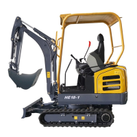
The Eurotrac HE18 mini excavator is designed for various earth-moving tasks, including loosening, excavating, lifting, transporting, and depositing soil, stones, and other materials. It can also be used for leveling work and with a hydraulic hammer. The machine is equipped with an adjustable undercarriage, allowing it to operate in both standard and narrow track widths for navigating confined spaces. The excavator features a speed-controlled automated transmission that automatically shifts between fast and normal driving speeds depending on the load.
The control elements are hydraulically operated, with a pilot circuit for most functions, ensuring precise control. The dozer blade lever, boom swing pedal, extra circuit pedal, and drive levers are exceptions, with the dozer blade controlled via a Bowden cable. Safety features include a protective structure (ROPS, TOPS, OPG) for the operator, an emergency hammer for cab models, and a locking mechanism for the superstructure to prevent unintentional rotation during transport.
Model: HE18 Type: Rubber track Machine weight (with standard bucket, operational readiness accomplished): 1760 kg Bucket Volume (CECE): 0.040 m³ Bucket Width (without side teeth): 452 mm Bucket Width (with side teeth): 472 mm
Engine:
Power:
Dozer blade:
Extra-circuit connection:
Volume of the fuel tank: 21 l
Noise level:
Vibrations (Hand-arm system, ISO 5349-2:2001):
Vibrations (Complete, ISO 2631-1:1997):
Lift Capacity (Structural): Based on ISO 10567, not greater than 75% of static tipping load or 87% of hydraulic carrying capacity. The maximum lift capacity when rotating 360° varies depending on the boom and dozer blade position.
Driving Position: The operator's seat is centrally located, with left and right control consoles, drive levers, and a pedal mechanism. The left control console includes a locking mechanism for control levers, a wrist support, and the left control lever for superstructure and arm movements. The right control console features an extra circuit rocker switch, fast driving position push-button, dozer blade lever, starter switch, engine speed lever, windshield wiper/spray switch (cab model), fan switch (cab model), wrist support, and the right control lever for boom and bucket movements.
Undercarriage Width Adjustment: The track width can be adjusted from a standard 1300 mm to a narrow 990 mm for tight spaces. Excavating should always be done with the standard track width for stability.
Starting the Engine: The engine speed lever should be pushed towards the "rabbit" symbol. The ignition key is inserted into the starter switch and turned to the RUN position. The engine can only be started if the left control console is raised. The excavator has theft protection, and an incorrect key will trigger a warning light.
Driving the Excavator: Both drive levers are pushed forward for forward movement and pulled back for reverse. Releasing the levers stops the excavator. The fast driving position push-button allows for faster movement. Driving on muddy or uneven ground at high speed is prohibited. Turning is achieved by pushing or pulling the drive levers in opposite directions.
Excavation: The dozer blade is raised by pulling its lever back and lowered by pushing it forward. The left control lever swings the arm out/retracts it and turns the superstructure left/right. The right control lever raises/lowers the boom and retracts/swings out the bucket.
Extra Circuit (Option): The extra circuit rocker switch controls oil flow to attachments. It can be controlled proportionately. The direct return changeover valve allows hydraulic oil to return either via the valve block or directly to the hydraulic oil tank, depending on the attachment used.
Cab Features (Cab Model): Includes interior lighting, windshield cleaning system, and heating. The windshield can be opened and secured upwards. Side windows can be slid open.
Winter Use: For temperatures below 5 °C, specific measures include using winter-specific engine and hydraulic oil, checking battery charge, topping up antifreeze, lubricating rubber gaskets and locks, and filling the windshield washer system with frost-free fluid.
The manual provides a detailed maintenance schedule with daily, monthly (200 hours), 3 months (600 hours), 6 months (1200 hours), and annually (2400 hours) intervals.
Daily/Regular Checks:
Scheduled Maintenance:
Maintenance Products: The manual specifies recommended viscosities, quality standards, brands, and types for engine oil, coolant, grease, hydraulic oil, and transmission oil.
Repairs: Only trained personnel are authorized to perform repairs. Welding on chassis parts must be checked by an expert. The machine should only be put back into operation after repairs if it can be guaranteed to run without failure.
Technical Safety Check: Regular technical safety checks must be performed by qualified personnel according to national standards. The checks include visual and functional inspections, with documentation of results and any defects.
| Brand | Eurotrac |
|---|---|
| Model | HE18 |
| Category | Excavators |
| Language | English |