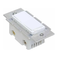
3-Way Wi-Fi Smart Dimmer Switch
Meet your new smart switch !
wallplate x1 wiring x1 screws x2
• WF31 •
Power: 120V AC, 60Hz
Wireless Frequency: 2.4GHz
Wireless Standard: IEEE802.11b/g/n
Maximum Load: 150W LED, 500 W
incandescent
Minimum Load: 5W for LED bulbs
Range: Up to 100 feet line of sight
For indoor use.
Part 1. Installation
Switch x1
Contents
A quick note before we give out the wiring schematics. Please do not try installing this device if you are unsure of how electrical circuits operate
within your home. As exciting as it is to have a smart switch installed, it can be dangerous and even life-threatening if you do not install this
A Few Quick Reminders
Note before installation
1) The Wi-Fi In-wall Smart Switch must not exceed 150W LED, 500W incandescent.
2) The switch box required: 1-gang U.S. wall box.
3½ in deep recommended, 2¼ in deep minimum.(The switch is designed only for use
with permanently installed fixtures.)
3) Work with
regular 3-way on/off don't use a smart
switch or a dimmer switch! Couldn't work with an add-on switch!
4) The colors of your wires may not match the ones in our diagrams so please make sure you've
identified all wires correctly based on
their source, not color only.
5) Please check your original 3-way wiring circuit in your home before installation, and then
follow the wiring diagram option 1 or 2 in
the manual.
6) Install the smart switch in the switch box which directly connects to the power Line and Neutral.
7) This switch
requires a Neutral for installation, or the installation will not succeed.
8) Not recommended for fan.
Convention Description Convention Description
• Adding your device to Wi-Fi network
• LED Indicator Status Setting
• Restore State aer Power Failure
• Light Off State Setting
• Button Function Setting
Function description
• Download the app
• Add a device in your app
• Work with Amazon Echo & Google Home
• If you cannot configure it by the default mode
successfully, try to connect by AP mode.
• LED Indicator/ Button function
• Adding / reset the device ( Factory setting)
• Min & Max Brightness Value Setting
• Wiring Instructions
• single pole and 3-way wiring diagram
• Pre-installation preparation
• Installation steps
Part 1.
Installation
Part 2.
Wiring Diagram
Part 3.
Manual Control
For more detials, please refer to the manual parts.
If you have any questions during installation,
Please contact us ask@nie-tech.com
Part 6.
Parameter Settings
Part 5.
Network Configuration
Part 4.
APP Connection
CHANGING THE COLOR OF THE PADDLE(OPTIONAL)
This step is optional. Before you start you may want to change the color of the paddle to match your wallplate or decor.
2. Simply put the new paddle onto the switch by side tabs and snap securely into place.Once this step has been completed
please proceed to part 2 wiring.
Air-Gap Switch:
to the LED. Pull up for Bulb replacement, push down for normal use.
HOW TO INSTALL THE WIRES
3.
STRIP WIRE AT 3/8-1/2”
1. Unscrew: carefully turn the screw counterclockwise to leave enough space for
the wire to be inserted. Do not unscrew the screws completely.
2. Press down: Once loosened, use your finger so it catches the thread.
3. Insert the wire: make sure the wire is completely straight, then insert it into the
terminal while holding down the screw. Do not wrap the wire around the screw!
4. Tighten: Turn the screw clockwise to tighten the wire. Make sure the
wires are locked!
Note: There are 2 holes for each terminal can be used in the
connection.You can use a jump wire or the second hole at the
terminal to connect.
2.
If you have any questions, please contact us at
ask@nie-tech.com
Line (hot) — black (connected to power)
Neutral — white
Load — black (connected to lighting)
Traveler — red/other
(only in 3-way installations)
Line
Load
Ground
Traveler
Neutral
Single-pole wiring
3-Way switch option 1
1) Neutral required. If the box do not have a Neutral,
please stop! Connect the white wire to neutral
terminal(use a white jump wire form the package or
the second hole at the terminal to connect.)
2) Insert the Line wire to Line terminal and Load wire to
Load terminal. LOAD and LINE Can’t be swapped,
please make sure to identify them correctly!
IMPORTANT
1. Tool: Please prepare a flat head screwdriver.
2.
Turn power OFF at circuit breaker or fuse box.
3. Remove wallplate.
4. Remove the switch mounting screws.
5. Disconnect the wires and label them aer
remove the old switch.(Please use our sticker)
6. Carefully remove the switch from the switch
box. (DO NOT disconnect the wires.)
7. There are up to five screw terminals on the
smart switch, these are marked (Please check
<HOW TO INSTALL THE WIRES>)
8. Fix the wallplate with screws aer wiring
succeed. (Please use our screws.)
9.The Ground was excluded from the diagram to
simplify the illustration. Please Make sure all
ground wires are connected to all switches
respectively.
Line
Load
GroundNeutral
Traveler
(Just for 3-way switch)
1) Neutral required. If the switch box do
not have a Neutral, please stop!
Connect the white wire to neutral
terminal (use a white jump wire form
the package or the second hole at the
terminal to connect.)
2) Insert the Line wire to Line terminal
and Load wire to Load terminal.
LOAD and LINE Can’t be swapped,
please make sure to identify them
correctly!
3) Install the smart switch in the switch
box which directly connects to the
power Line, Load and Neutral.
4) Only work with regular 3-way on/off
for 2 locations control. It can only be
switch, don't use a smart switch or a
dimmer switch! Couldn't work with
an add-on switch!
Power
Power
regular
Line
Load
Neutral
From source
Ground
Load
Neutral
Line
Traveler
Line
Load
Neutral
From source
Neutral
regular 1
regular 2
common
common
Line
Load
Neutral
Traveler
From source
Ground
Load
Neutral
Line
Traveler
regular
common
None-connection
Line
Load
Neutral
Traveler
From source
1.
4.
( Line/Hot Neutral and Light/Load)
(3-way switch)
(3-way switch)
Box 1
Box 2
IMPORTANT
Neutral
Line
Neutral
Line
Smart
Switch
OUT TO LIGHT
OUT TO LIGHT
OUT TO LIGHT
OUT TO LIGHT
Part 2. Wiring Diagram
Neutral
Line
Neutral
Line
Smart
Switch
common
common
common