EVCO S.p.A. | EVJ LCD | Instruction sheet ver. 3.2 | Code 104VJLCDE323 | Page 1 of 2 | PT 16/19
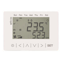
EVJ LCD
Remote user interfaces (with INTRABUS or RS-485 port)
EN
ENGLISH
- panel or wall mounting with or without back-slot for in-wall box (according to the mod-
el)
-
12 VAC/DC power supply not insulated or 115... 230 VAC power supply (according to the model)
- one or two NTC external analog inputs (according to the model)
- two digital outputs rated 1 res. A @ 250 VAC (according to the model)
- alarm buzzer
- incorporated temperature and humidity sensor (according to the model)
- incorporated Bluetooth Low Energy sensor (according to the model)
- INTRABUS port or RS-485 port with INTRABUS or MODBUS communication protocol
(according to the model)
- device for indoor applications.
Purchasing codes
mode
Power
supply
External
analog
inputs
Digital
outputs
and humidity
sensor
Bluetooth
Low Energy
sensor
EVJD900N2
panel
mounted
(black
front)
12 VAC/DC
no no no no
EVJD900N2VW
wall
mounted
(white
front)
12 VAC/DC
1 no
no
no
EVJD900N2VWTX
(1)
1 no no
EVJD900N2VWIV 1 no yes
EVJD920N2VW 1 no
yes
no
EVJD920N2VWSX
(2)
1 no no
EVJD920N2VWIV 1 no yes
EVJD902N9VP
with back-s
for flush
mounting box
(white front)
115... 230
VAC
2 2
no
no
EVJD902N9VPIV 2 2 yes
EVJD922N9VP 2 2
yes
no
EVJD922N9VPIV 2 2 yes
(1)
with RS-485 port with INTRABUS communication protocol
(2)
with RS-485 port with MODBUS communication protocol
1 MEASUREMENTS AND INSTALLATION | Measurements in mm (in)
1.1 Models for panel mounting
To be fitted to a panel, with elastic holding flaps.
N.B.
- the thickness of a metal panel must be between 0.8 and 1.5 mm (1/32 and 1/16
in), while that for a plastic panel must be between 0.8 and 3.4 mm (1/32 and
1/8 in)
- the measurements of drilling template must be 107.6 x 72.6 mm (3 15/16 x 2
7/8 in), with rounded corners R 3.0 mm (1/8 in).
1.2 Models for wall mounting
Wall mounting (with bolts and fastening screws) or in the most common flush mounting boxes
(with fastening screws).
1. Unhook the back shell from the front through a screwdriver and the proper seat.
2.1 In case of wall mounting:
2.1.1 Lean the back shell against the wall in a position suitable to get the connecting
cable to pass through the proper opening.
2.1.2 Use the slots of the back shell as template to drill 4 holes having a diameter
suitable to the bolt.
5.0 mm (3/16 in) diameter bolts are suggested.
2.1.3 Insert the bolts in the holes drilled in the wall.
2.1.4 Fasten the back shell at the wall with 4 screws.
Countersunk head screws are suggested.
2.2 In case of flush mounting box, fasten the back shell at the box with 4 screws.
Countersunk head screws are suggested.
3. Make the electrical connection as shown in the section ELECTRICAL CONNECTION with-
out powering up the device.
4. Fasten the front of the device at the back shell.
1.3 Models for wall mounting with back-slot for in-wall box
Wall mounting in the most common flush mounting boxes (with fastening screws).
1. Unhook the back shell from the front through a screwdriver and the proper seat.
2. Fasten the back shell at the box with 4 screws.
Countersunk head screws are suggested.
3. Make the electrical connection as shown in the section ELECTRICAL CONNECTION with-
out powering up the device.
4. Fasten the front of the device at the back shell.
INSTALLATION PRECAUTIONS
- Ensure that the working conditions are within the limits stated in the TECHNICAL
SPECIFICATIONS section
- Do not install the device close to heat sources, equipment with a strong magnetic field,
in places subject to direct sunlight, rain, damp, excessive dust, mechanical vibrations
or shocks
- In compliance with safety regulations, the device must be installed properly to ensure
adequate protection from contact with electrical parts. All protective parts must be
fixed in such a way as to need the aid of a tool to remove them.
2 ELECTRICAL CONNECTION
N.B.
- Use cables of an adequate section for the current running through them
- To reduce any electromagnetic interference connect the power cables as far away
as possible from the signal cables and connect to an INTRABUS network by using a
twisted pair.
2.1 Models for panel mounting
2.1.1 Connectors and parts
Connector 1
N.
DESCRIPTION
1 INTRABUS port reference (GND)
2 INTRABUS port data (IB)
3
device power supply (12 VAC/DC). If the device is fed by DC power, connect terminal
minus
4
device power supply (12 VAC/DC). If the device is fed by DC power, connect terminal
plus
Connector 2: reserved EVCO.
2.1.2 Electrical connection with independent power supply
N.B.
- Do not supply another device with the same transformer
- The maximum permitted length for connection cables of the INTRABUS port is
30 m (98.4 ft).
2.1.3 Electrical connection with device powered by a controller (for example
c-pro 3 OEM)
N.B.
- Make sure that the current supplied by the controller is within the limits stated in
the TECHNICAL SPECIFICATIONS section
- The maximum permitted length for connection cables of the INTRABUS port is
10 m (32.8 ft).
2.2 Models for wall mounting
2.2.1 Connectors and parts
Connector 1
No.
DESCRIPTION
1 INTRABUS port reference (GND) or RS-485 signal B (-) (according to the model)
2 INTRABUS port data (IB) or RS-485 signal A (+) (according to the model)
3
device power supply (12 VAC/DC). If the device is fed by DC power, connect terminal
minus
4
device power supply (12 VAC/DC). If the device is fed by DC power, connect terminal
plus
5 AI4 analog input (NTC)
6 AI4 analog input reference (GND)
Connector 2: reserved EVCO.
Micro-switch: in models with RS-485 port, to insert the RS-485 port termination resistor (not
present otherwise).
Temperature (AI3) and humidity (AI5) sensor: according to the model.
Bluetooth Low Energy sensor: according to the model.
2.2.2 Electrical connection with independent power supply
N.B.
- Do not supply another device with the same transformer
- The maximum permitted length for connection cables of the INTRABUS port is
30 m (98.4 ft), 1,000 m (3,280 ft) in models with RS-485 with INTRABUS or MOD-
BUS communication protocol.
2.2.3 Electrical connection with device powered by a controller (for example
c-pro 3 OEM)
N.B.
- Make sure that the current supplied by the controller is within the limits stated in
the TECHNICAL SPECIFICATIONS section
- The maximum permitted length for connection cables of the INTRABUS port is
10 m (32.8 ft).