EVCO S.p.A. | EVJ LCD | Instruction sheet ver. 1.0 | Code 104JLCDA103 | Page 1 of 2 | PT 50/16
EVJ LCD
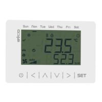
Remote user interfaces
EN
ENGLISH
- 12 VAC/DC power supply not insulated
- alarm buzzer
- models with incorporated Bluetooth Low Energy sensor
- models with incorporated temperature and humidity sensor
- INTRABUS port
- device for indoor rooms.
Purchasing code
incorporated Bluetooth
Low Energy sensor
incorporated temperature
and humidity sensor
EVJD900N2VWIX no no
EVJD900N2VWIV yes no
EVJD920N2VWIX no yes
EVJD920N2VWIV yes yes
1 MEASUREMENTS AND INSTALLATION
Measurements in mm (inches).
Wall mounting (with bolts and fastening screws) or in 502E or 503E flush mounting box (with
fastening screws).
1. Unhook the back shell from the front through a screwdriver and the proper seat.
2.1 In case of wall mounting:
2.1.1 Lean the back shell against the wall in a position suitable to get the connecting
cable to pass through the proper opening.
2.1.2 Use the slots of the back shell as template to drill 4 holes having a diameter
suitable to the bolt.
5.0 mm (3/16 in) diameter bolts are suggested.
2.1.3 Insert the bolts in the holes drilled in the wall.
2.1.4 Fasten the back shell at the wall with 4 screws.
Countersunk head screws are suggested.
2.2 In case of 502E or 503E flush mounting box, fasten the back shell at the box with 4
screws.
Countersunk head screws are suggested.
3. Make the electrical connection as shown in the section ELECTRICAL CONNECTION with-
out powering up the device.
4. Fasten the front of the device at the back shell.
INSTALLATION PRECAUTIONS
- Ensure that the working conditions are within the limits stated in the TECHNICAL
SPECIFICATIONS section
- Do not install the device close to heat sources, equipment with a strong magnetic field,
in places subject to direct sunlight, rain, damp, excessive dust, mechanical vibrations
or shocks
- In compliance with safety regulations, the device must be installed properly to ensure
adequate protection from contact with electrical parts. All protective parts must be
fixed in such a way as to need the aid of a tool to remove them.
2 ELECTRICAL CONNECTION
N.B.
- Use cables of an adequate section for the current running through them
- Connect to a INTRABUS network by using a twisted pair.
2.1 Connectors and parts
Description.
Connector 1
No.
DESCRIPTION
1 reference INTRABUS port
2 signal INTRABUS port
3
device power supply (12 VAC/DC). If the device is fed by DC power, connect terminal
minus
4
device power supply (12 VAC/DC). If the device is fed by DC power, connect terminal
plus
5 reserved
6 reserved
Connector 2
USB port.
Bluetooth Low Energy sensor
Only available in EVJD900N2VWIV and EVJD920N2VWIV.
Temperature and humidity sensor
Only available in EVJD920N2VWIX and EVJD920N2VWIV.
Connector 2
No.
DESCRIPTION
1 signal + CAN port
2 signal - CAN port
3 reference (GND)
2.2 Electrical connection
Example of electrical connection.
2.3 Pre-setting for the programming
To pre-set the device for the programming, place micro-switch 1 in position ON.
PRECAUTIONS FOR ELECTRICAL CONNECTION
- If using an electrical or pneumatic screwdriver, adjust the tightening torque
- If the device has been moved from a cold to a warm place, the humidity may have
caused condensation to form inside. Wait about an hour before switching on the power
- Make sure that the supply voltage, electrical frequency and power are within the set
limits. See the section TECHNICAL SPECIFICATIONS
- Disconnect the power supply before doing any type of maintenance
- Do not use the device as safety device
- For repairs and for further information, contact the EVCO sales network; possible re-
turns without back shell will not be accepted.
3 USER INTERFACE
3.1 Device configuration
N.B.
Turn off the power after changing the configuration.
Accessing the procedure.
1.
Touch the DOWN key for 7 s.
The display will show:
Upper line Menu
Lower line InFo
Accessing the menu.
2.
Touch the UP or DOWN key to select a menu.
The display will show:
Upper line Menu
Lower line menu name.
3.
Touch the SET key.
The display will show:
Upper line the parameter
Lower line the parameter value
Setting configuration parameters of menu “PAr”.
3.
Touch the SET key.
The display will show:
Upper line PSU
Lower line 0000
4.
Touch the SET key again.
The display will show:
Upper line PUSU
Lower line a value flashing
5.
Touch the UP or DOWN key to set “-019”.
6.
Touch the SET key.
7.
Touch the UP or DOWN key to select a parameter.
The display will show:
Upper line the parameter
Lower line the parameter value
8.
Touch the SET key.
The display will show:
Upper line the parameter
Lower line the parameter value flashing
9.
Touch the UP or DOWN key to set the value.
10.
Touch the SET key.
Returning to the previous displays.
11.
Touch the ON/STAND-BY key a few times.
4 CONFIGURATION PARAMETERS
N. PAR. DEF. “InFo” MENU (READ ONLY) MIN... MAX.
1 Prn - project number -
2 Pru - project version -
3 Prr - project revision -
4 FUu - firmware version -
5 FUr - firmware revision -
6 FUS - firmware subversion -
7 HUu - hardware version -
8 HUr - hardware revision -
N. PAR. DEF. “PAr” MENU MIN... MAX.
9
BKIL
10
backlight intensity
0... 100
15 uneditable in
EVJD920N2VWIX and
EVJD920N2VWIV
10
BKIt
241
backlight timeout
0... 241 s
241 = always lit
30 uneditable in
EVJD920N2VWIX and
EVJD920N2VWIV
11
EU3C
OFF enable compatibility with Vled 3 On... OFF
N. PAR. DEF.
“nEt > IbuS” MENU (READ ONLY)
MIN... MAX.
12
nOdE
4
INTRABUS node
1... 127
if EU3C = On, nOdE = 3
13
StAt - INTRABUS status communication
OK... Err
14
n_rH
-
number of received INTRABUS
packages
0... 999
15
n_tH
-
number of transmitted INTRA-
BUS packages
0... 999
16
nErr
-
number of INTRABUS receipts in
error
0... 999
17
BAud
- INTRABUS baud rate 19200
18
StPB 1 INTRABUS bit stop number 0... 2
19
PrtY 2 INTRABUS parity 0... 2
N.
PAR.
DEF.
“nEt > bLE” MENU (READ ONLY;
AVAILABLE IN EVJD900N2VWIV
AND EVJD920N2VWIV)
MIN... MAX.
20
n_rH
-
number of BLE packages re-
ceived
0... 999
21
n_tH
-
number of BLE transmitted re-
ceived
0... 999
22
nErr
-
number of intercepted BLE er-
rors
0... 999
23
BAud
- BLE baud rate 19200
24
StPB 1 BLE bit stop number 0... 2
25
PrtY 2 BLE parity 0... 2
N. PAR. DEF. “diAG” MENU (READ ONLY) MIN... MAX.
26
MEm - EEPROM memory status OK... Err
27
PSU - power supply voltage status OK... Err
N. PAR. DEF. “dEb” MENU MIN... MAX.
28
PSU - power supply voltage value -
29
AI1 - reserved -
30
AI2 - reserved -
31
AI3 - reserved -
32
AI4 - reserved -
33
tI2C
-
incorporated sensor temperature
value
-
34
HI2C
-
incorporated sensor humidity va-
lue
-
N. PAR. DEF. “dEb > un” MENU MIN... MAX.
35
dO1 - reserved -
36
AI1t - reserved -
N. PAR. DEF. “ConF” MENU MIN... MAX.
37
PSU - reserved -
5 TECHNICAL SPECIFICATIONS
Purpose of the control device:
Function controller.
Construction of the control device:
Built-in electronic device.
Container:
White, self-extinguishing.
Category of heat and fire resistance:
D.
Measurements: 111.4 x 76.4 x 18.5 mm (4 3/8 x 3 x 3/4 in).
Mounting methods for the control device:
Wall mounting (with bolts and fastening
screws) or in 502E or 503E flush mounting
box (with fastening screws).
Degree of protection provided by the cover-
ing:
IP30.
Connection method:
Fixed screw terminal blocks for wires up to
1 mm²
Female Micro USB connector.
Maximum permitted length for connection cables:
Power supply: 10 m (32.8 ft)
USB port: 1 m (3.28 ft)
INTRABUS port: 10 m (32.8 ft).
Operating temperature:
From 0 to 40 °C (from 32 to 104 °F).
Storage temperature:
From -20 to 70 °C (from -4 to 158 °F).
Operating humidity:
Relative humidity without condensate from 5
to 95%.
Pollution status of the control device:
2.
Compliance:
RoHS 2011/65/EC
WEEE 2012/19/EU
REACH (EC) Regulation no. 1907/2006
EMC 2014/30/UE R&TTE 1999/5/CE.
Power supply:
12 VAC/DC
12 VAC (±15%), 50/60 Hz (±3 Hz), max.
10 VA not insulated
12 VDC (±15%), max. 10 W not insulated.
Earthing methods for the control device:
None.
Rated impulse-withstand voltage:
4 KV.
Over-voltage category:
III.
Software class and structure:
A.
Displays: Two rows and function icons LCD display.
Alarm buzzer:
Built-in.
Incorporated sensors:
Bluetooth Low Energy (only in
EVJD900N2VWIV and EVJD920N2VWIV)
temperature and humidity (only in
EVJD920N2VWIX and EVJD920N2VWIV).
Working range incorporated temperature and humidity sensor:
0... 40 °C (32... 104 °F) 10... 90 % of relative humidity.
Communications ports:
1 INTRABUS port
1 USB port.