The Evenlite Central Inverter System is designed to provide emergency power, ensuring that critical systems remain operational during power outages. This Contractors Guide outlines the installation process for a 2,200 Watt/VA, two-phase, split-phase inverter system, which can be configured for both vertical (stacked) and horizontal (side-by-side) mounting. The system is built with reliability in mind, emphasizing robust construction and clear installation procedures to ensure its "Lives Depend On Us" motto is upheld.
Function Description:
The Evenlite Central Inverter System acts as an uninterruptible power supply (UPS) for emergency lighting and other critical loads. In the event of a main power failure, the inverter seamlessly switches to battery power, providing continuous AC output to connected circuits. This ensures that essential services, such as emergency egress lighting, remain active, complying with safety regulations and maintaining operational continuity. The system is designed for central installation, meaning it powers multiple emergency circuits from a single location, simplifying maintenance and management compared to distributed emergency lighting solutions. The inverter's output is a two-phase, split-phase AC power, suitable for a wide range of commercial and industrial applications.
Important Technical Specifications:
- Power Rating: 2,200 Watt/VA. This indicates the maximum continuous power the inverter can supply to connected loads.
- Phase Configuration: Two-phase, split-phase. This refers to the type of AC output provided, commonly used in North American electrical systems for both 120V and 240V loads.
- Mounting Options:
- Vertical (Stacked): The battery cabinet is mounted directly underneath the electronics cabinet. This configuration is factory-preferred and optimizes space utilization, especially in areas with limited floor space. The overall height for a stacked configuration is approximately 64.3 inches (55.6 inches for the electronics cabinet and 8.7 inches for the battery cabinet, including mounting brackets).
- Horizontal (Side-by-Side): The battery cabinet is mounted to the right side of the electronics cabinet. This configuration is suitable when height restrictions are a concern or when a wider footprint is acceptable. The overall width for a horizontal configuration is approximately 48 inches (24 inches for each cabinet).
- Battery Voltage: Nominal DC voltage of 48VDC. The system uses 8 batteries, connected in a series-parallel arrangement to achieve this voltage. Each battery shelf accommodates two battery strings, with each string comprising four batteries wired in series.
- Clearance Requirements: A minimum of 3 feet (36 inches) clearance is required in front of all units to allow for proper ventilation, maintenance access, and operation of the Man Machine Interface Panel.
- Cabinet Dimensions (approximate):
- Electronics Cabinet (Master Inverter Cabinet): Approximately 24 inches wide, 38 inches high, and 13 inches deep.
- Battery Cabinet: Approximately 24 inches wide, 38 inches high, and 13 inches deep.
- Knock-Outs: Provided on the tops and sides of the inverter cabinet for AC conduit entry. These are dual-sized for 7/8" and 1-1/8" diameter conduits. There are 16 dual knockouts on the top and multiple on the sides (4x 2.50 on top, 2x 1.75 on top, 4x 1.75 on side).
- Battery Cable Lengths: Critical for proper operation and must be trimmed to length when using vertical (stacked) mounting.
- AC Breaker Panel: Integrated into the Master Inverter Cabinet, with an AC Input Breaker CB1 and optional Output Circuit Breakers (CB2, CB3).
- Wiring: Input and Output Wires should be run in separate conduits per NEC requirements.
- Fasteners:
- Floor mounting brackets use (8x) 1/4-20 flange bolts.
- Battery cabinet to inverter cabinet stacking uses (6x) 1/4-20 bolts.
- Floor mounting bolt pattern includes .31 Dia. holes for 1/4" hardware.
Usage Features:
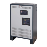
- Man Machine Interface Panel: Located on the Master Inverter Cabinet, this panel provides a user interface for monitoring system status and managing operations. The "System's On/Off Switch" is located to the right of this panel.
- Step-by-Step Installation Guide: The manual provides a clear, five-step process for installation:
- Mounting the Cabinet: This involves securing the cabinets to the floor using provided floor mounting brackets and ensuring the surface is level. For vertical mounting, the floor mounting brackets are removed from the inverter cabinet, and the battery cabinet is secured underneath. For horizontal mounting, the battery cabinet is placed to the right of the electronics cabinet. Concrete wedge anchors or other suitable methods are used for floor anchoring.
- Installing and Wiring the Batteries: This critical step involves installing 8 batteries onto the battery shelves and connecting them according to the provided schematic. Battery cable lengths must be precisely trimmed, and proper spacing between batteries is essential. Battery Buss Bars are used for connections.
- Installing the AC Conduit: Utilizes pre-provided knock-outs on the cabinet tops and sides. Users are explicitly warned against drilling into the cabinets to avoid voiding the warranty and potential damage from metal shavings.
- Installing the AC Wiring: Involves connecting AC Input, Output, and Neutral wires to the terminal blocks within the inverter cabinet. The AC Input Breaker CB1 is positioned for easy access. Separate conduits for input and output wires are mandated.
- Starting Up/Energizing the Unit: This final step involves verifying all installations, ensuring AC power is present, flipping the input circuit breaker, and then the system's On/Off switch. A system test button is available to confirm proper operation.
- Flexible Battery Cable Routing: Designed to accommodate both vertical and horizontal configurations, ensuring proper cable management from cabinet to cabinet.
- Modular Design: The system consists of two main cabinets (Master Inverter Cabinet and Battery Cabinet), allowing for flexible installation and potential future expansion or maintenance.
- Safety Features: Includes an AC Breaker Panel for protection and clear instructions for safe wiring practices. The warning against drilling into cabinets highlights the importance of preserving the integrity of electronic components.
Maintenance Features:
- Easy Access: The design allows for relatively easy access to internal components, such as batteries and wiring, for maintenance and inspection. The 3-foot clearance requirement facilitates this.
- Replaceable Components: The system is designed with components that can be replaced, such as batteries and circuit breakers, extending the lifespan of the unit.
- Clear Wiring Diagrams: Detailed illustrations for battery wiring and AC wiring simplify troubleshooting and maintenance tasks.
- Technical Support: Evenlite provides dedicated technical support and installation assistance via phone (1-800-967-5573) during business hours (Monday-Friday, 8 AM-5 PM EST), ensuring professional help is available for any issues.
- Installation/Operation Manual: A comprehensive manual is referenced for additional information, serving as a primary resource for detailed maintenance procedures and operational guidelines.
- Grommets: Installable grommets in the battery cabinet are used for wire protection before stacking, preventing chafing and damage to cables.
- Floor Mounting Brackets: These are removable for vertical mounting, simplifying the configuration change and reducing unnecessary components.
The Evenlite Central Inverter System is a robust and versatile emergency power solution, designed with ease of installation, operational reliability, and maintainability in mind, making it suitable for critical applications where continuous power is paramount.