Do you have a question about the Evoqua WALLACE & TIERNAN 700 P and is the answer not in the manual?
Provides information on the manual's structure, target audience, and safety instructions.
Explains symbols and their meanings used throughout the manual for clear communication.
Specifies the designated purpose and application scope for the 700 P electronics module.
Provides essential safety guidelines and warnings for handling and operating the device.
Details safety precautions for different operational stages like normal use and maintenance.
Outlines the requirements that must be met to ensure warranty validity.
States the manufacturer's limitations of liability regarding damages during installation or use.
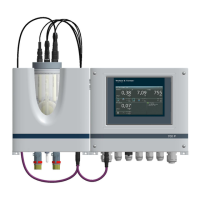
Introduces the 700 P electronics module as part of the Pool Management System and its primary functions.
Explains the configuration options and variant codes for the 700 P electronics module based on customer requirements.
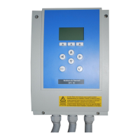
Details the physical components and construction of the 700 P electronics module, including housing and internal parts.
Describes the capabilities and typical applications of the 700 P electronics module in pool management.
Provides detailed specifications for the 700 P electronics module, including dimensions, power, and environmental conditions.
Explains the CAN interface functionality, connection, and its role as a sensor bus.
Details the RS485 interface for data transfer to superordinate systems and its integration into bus systems.
Describes the USB interface for data export, firmware updates, and parameter management.
Covers connection to superordinate fieldbus systems like Profibus DP.
Explains the LAN port for network access, remote operation via VNC, and Modbus TCP communication.
Details the integrated Modbus TCP interface for data communication via Ethernet.
Specifies the data formats used for process data transmission via Modbus TCP.
Lists the items included with the 700 P electronics module and optional components.
Provides guidelines for safe handling, transport, and storage of the device to maintain its condition.
Outlines necessary environmental conditions for correct and safe operation of the module.
Covers the physical mounting procedures for the module, including options and details.
Details the safe and correct procedures for wiring the 700 P electronics module to the power supply.
Outlines the steps and requirements for safely starting up and configuring the 700 P electronics module.
Provides instructions for safely disconnecting and powering down the 700 P electronics module.
Refers to the commissioning section for procedures on restarting the device.
Explains the functions of the color graphic display and touch panel for user interaction.
Introduces the available menus for measurements, controls, and system settings on the module.
Details the procedures for calibrating sensors (chlorine, pH, ORP, conductivity) for accurate measurements.
Lists possible error messages, their causes, and recommended solutions for troubleshooting.
Specifies the recommended schedule for performing maintenance tasks on the module.
Provides step-by-step instructions for safely replacing fuses on the A&C board.
Guides users on how to safely replace the real-time clock battery.
Advises on proper cleaning methods for the device, recommending mild detergents.
Lists available optional components for upgrading the module's functionality.
Explains the process of installing mA output cards or relay boards.
Provides a list of part numbers for essential spare components of the 700 P electronics module.
Lists available manuals for the 700 P module and associated flow cells in different languages.
Presents the EC declaration confirming compliance with relevant European directives.
Shows the CSA certificate indicating compliance with North American safety standards.
| Model | 700 P |
|---|---|
| Category | Control Systems |
| Manufacturer | Evoqua (WALLACE & TIERNAN) |
| Gas | Chlorine |
| Power Supply | 50/60 Hz |
| Materials of Construction | PVC |
| Communication Protocol | Modbus |