Do you have a question about the Evoqua WALLACE & TIERNAN SFC and is the answer not in the manual?
Defines the SFC's exclusive purpose for measurement and control in water treatment.
Outlines Evoqua's commitment to safety and the importance of observing instructions.
Highlights specific dangers related to electrical power and agents/chemical substances.
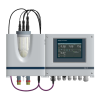
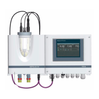
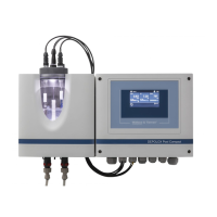
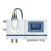
Introduces the SFC as a measuring and control device for water treatment and its typical applications.
Lists the types of sensor modules and retrofit kits supported by the SFC for measurement.
Describes the mA output and relay outputs available on the SFC for control and signaling.
Explains how system configuration is determined by SFC version, parameters, components, and application selection.
Describes the operation mode for quantity-proportional dosing of disinfectants with process measurement.
Explains the operating mode for controlling a measured variable according to a setpoint.
Describes the compound loop, combining single feed forward with feedback control for accuracy.
Lists various controller types and their actions, such as positioners and dosing pumps.
Defines input variables that determine the control functions of a controller, listed alphabetically.
Explains how alarms are output via relay contacts and display indicators, with configurable functions.
Details the process for automatic ascertainment of control loop reaction times and parameters for Cl2 single feedback control.
Details the SFC's integrated CAN interface for connecting CAN sensor modules like SiDiSens.
Describes two methods for performing firmware updates: via serial interface or SD memory card.
Explains how actuator feedback signals are set at the factory and possible feedback signals.
Explains the use of an SD memory card for saving configurations and recording measured data.
Describes the SFC's ability to save unit settings as configurations, with options for internal memory and SD card storage.
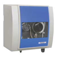
Details the installation site requirements and procedures for mounting the unit.
Outlines the process for commissioning the unit after installation, including equipping sensor modules and electrical connections.
Presents a step-by-step guide for commissioning the SFC, referencing specific chapters for detailed information.
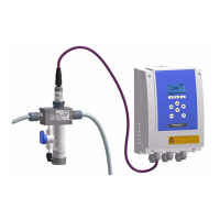
Explains how to insert and connect various sensors to the flow block assembly, noting maximum back pressure.
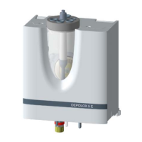
Guides on connecting sample water and initial startup procedures, using DEPOLOX® 5 as an example.
Provides critical safety warnings and instructions for connecting the SFC to the power supply.
Details the procedure for activating the SFC and the initial language setup during commissioning.
Explains how to select and program the appropriate application for the SFC system.
Guides on automatic or manual calibration of the positioner feedback signal for automatic positioning.
Describes how to calibrate positioner feedback points for linear dosing output in specific applications.
Provides crucial safety instructions and step-by-step procedures for safely shutting down the SFC system.
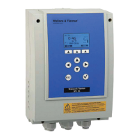
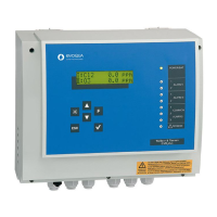
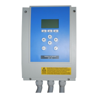
Describes the graphic display and the nine-key operating panel used to control the SFC.
Outlines the various menus available in the SFC, such as Main Menu, Control, and Calibration.
Shows the navigation path for accessing module type specific settings and calibration options.
Lists available settings for Module type 1, including control modes, setpoints, and actuator outputs.
Lists available settings for Module type 2, covering actuator, setup, measuring range, and limit values.
Illustrates navigation to the Inputs/Outputs menu for configuring flow rate, limit values, and setpoints.
Shows the navigation path to the Alarm menu for configuring alarm functions and assignments.
Describes the contact condition of alarm relays and delay settings for alarms 1 and 2.
Describes the contact condition of alarm relays and delay settings for alarms 3 and 4.
Illustrates navigation to the System menu for common settings, configuration, and safety.
Shows navigation to the Diagnosis menu for viewing diagnostics, module types, dosing averages, and I/O status.
Shows the navigation path to the Calibration menu for sensor calibration.
Illustrates navigation to the Operating mode menu for switching between AUTO and MANUAL modes.
Provides general guidelines and warnings for sensor measuring module calibration, including pre- and post-calibration tasks.
Provides detailed instructions for pH calibration, including pH-7 alignment and slope alignment.
Guides on performing Redox calibration, noting the long running-in times for Redox sensors.
Details the procedure for conductivity calibration, including temperature compensation and using calibration solutions.
Explains the two-point calibration process for fluoride measurement, including pre-use electrode preparation.
Lists common error messages, their causes, and recommended remedies for troubleshooting.
Lists common errors like no power, incorrect display values, low controller quality, and non-working positioners/pumps.
Provides safety warnings and step-by-step instructions for changing fuses on the A&C board.
Guides on replacing the backup battery for the real-time clock, noting its importance for time-controlled functions.
Outlines settings for measuring range, including range start and end values for various parameters.
Lists alarm functions, delays, and assignments for configuring alarm behavior.
| Capacity | Varies by model |
|---|---|
| Power Supply | Varies by model |
| Communication Protocol | Modbus |
| Enclosure Rating | NEMA 4X |
| Operating Temperature | 50°C (122°F) |
| Dimensions | Varies by model |
| Weight | Varies by model |