-
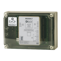
RB2000LT MLS Bus Power Supply - ‘Lite’
Only suitably qualified personnel should install this equipment.
The RB2000LT powers and synchronises the MLS Bus for up to 100 MLS devices. Wall switch inputs
allow simple dimming and on/off control over suitably programmed devices in the system. There is no
provision to link multiple RB2000LTs together.
Fixing
The RB2000LT is supplied in a protective housing which should be mounted where it is accessible for
commissioning purposes.
Connection
2
It is imperative that the MLS bus is wired with the correct type of cable; normally it should be 1.5mm
unscreened twisted pair. Please read Application Note AN4001 for more details. As the MLS Bus is
polarity-conscious, care must be taken to maintain polarity throughout.
Do not connect mains to the MLS bus as this will cause irreversible damage to all devices in the system.
2 2
The mains supply, MLS bus and switch input terminals are suitable for 1 x 4mm or 2 x 2.5mm cable.
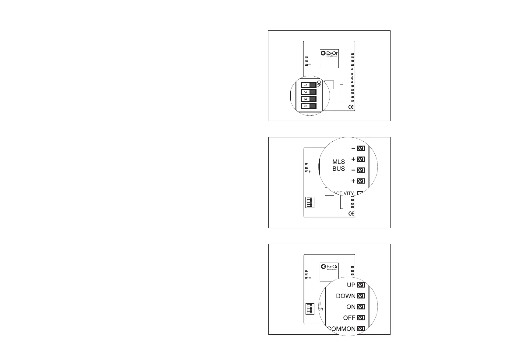
Centre-off, three-way, momentary wall switches should be connected to the ‘Wall Switch’ UP and
DOWN terminals. Centre-off, three-way, latching wall switches should be connected to the ON and OFF
terminals. Each command actioned by the switch is addressed to all devices programmed to operate on
either Zone 1 or Zone 2 of the MLS Bus System. All other Zones remain unaffected by the switch inputs.
Commissioning
The RB2000LT has two modes of operation, depending on what range of equipment the unit is being
used in conjunction with.
Located at the bottom, left-hand corner of the unit is a four-way DIL switch. Switch number 4 determines
what bus type is being used. For 1200 Series detectors and equipment (e.g. MLS1200DIS) this switch
should be set in the ON position. By default it is set to OFF - for use with 2000 Series equipment (e.g.
MLS2000PF).
Switch number 1, when set in the ON position, allows the RB2000LT to operate in ‘Commissioning’
mode. In this state, any detector or device in the system which is programmed to any zone (via an
HP2000) can then be turned OFF by infrared override. This override command will filter down to every
device in the system enabling the operator to see that the bus cabling is installed and functioning
correctly.
Switches 2 and 3 have no function.
1. 4-way DIL switch. All switches set to OFF by
default. Switch 1 enables commissioning
mode; Switch 4 determines bus type.
Switches 2 and 3 - no function.
2. MLS Bus connections. Do NOT connect
mains to the MLS Bus. Polarity must be
maintained.
3. Switch input connections.
Important Additional Notes
1. All terminals on this product are provided for final connections. It is not intended that the product be used as a junction box
for looping cables.
2. A means for disconnection must be incorporated in the fixed wiring in accordance with the current wiring regulations.
RB2000LT
Ex-Or Limited
Haydock Lane
Haydock
Merseyside
WA11 9UJ
UP
UP
DOWN
DOWN
ON
ON
OFF
OFF
COMMON
Switch 1 ON = Commissioning Mode
Switches 2 & 3 = No Function
Switch 4 ON = MLS1200 Series Bus
(default OFF = MLS2000 Series)
ON
1 2 3 4
ACTIVITY
Power Consumption <10W
o
Ambient Temperature Range 0 - 40 C
Maximum 100 Nodes per System
Do Not Connect Mains to the MLS Bus
Software Version
Wall
Switch
MLS
BUS
+
+
-
-
L
N
230V
50Hz
1
2
3
W4159C
 Loading...