2.2 Discharge recommendations
Do not exceed below current levels for discharging the battery. If fully discharged (0 % SOC or low voltage disconnect
by BMS) recharge without delay. Never leave the battery in a fully discharged state.
Currents higher than maximum allowed MUST BE AVOIDED since may shorten battery life or lead to premature
failure, and may damage the connected equipment if BMS protection occurs.
2.3 Charge recommendations
For maximum long-term performance and endurance of the battery, the standard charge method should be used.
Never charge the battery with voltages or currents above the MAX levels as listed in the tables below.
To recharge, use Exide approved Li-Ion charger or other Li-Ion battery charger (LFP) fulfilling charger
specifications as described in this section. To recharge a battery in low voltage protection mode, the charger must
be able to start charging from 0V. Make sure the charger is capable of activating also when battery voltage is 0V
(e.g. use power supply function, automatic starting function or similar setting). Note that some chargers do not have
this capability and will not be able to “wake up” a li-Ion battery from low voltage protection, refer to charge manual
for details and use a different charger if required.
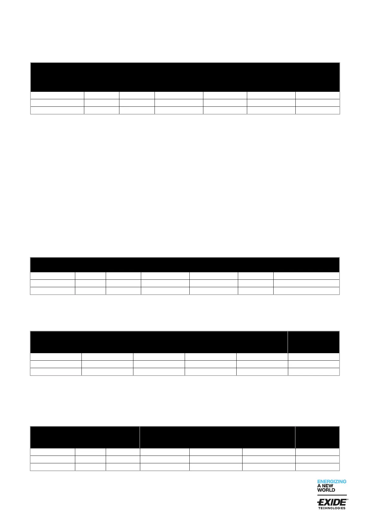
2.3.1 Standard charge
The standard charge method is IU- or IU0U profile using the current and voltage levels as listed below.
*The charging should be ended or continue with float charge voltage of 27.6 V when the cut-off current is reached.
It is not recommended to maintain the voltage above float charge level when the battery is fully charged.
2.3.2 Charging voltage ranges for IU- or IU0U profile
*Voltages higher than maximum allowed MUST BE AVOIDED since they may shorten battery life or lead to
premature failure, and may damage the connected equipment if BMS protection is triggered.
The higher end of the range is recommended to ensure full utilization of the battery capacity.
2.3.3 Charging current ranges IU- or IU0U profile
Do not exceed below current limits for recharging the battery.
C-rate, current (A) as a factor of rated capacity (Ah).
* Recommended current (A) to ensure maximum lifespan
 Loading...