EasyManua.ls Logo

Exit Stopper STI-6400 Series - User Manual

Exit Stopper STI-6400 Series
2 pages
Print Icon
To Next Page IconTo Next Page
Loading...
Exit Stopper
®
Quick Install
STI-6400 Series
Rely on STI
®
SET UP
1. Key in OFF position
3. Remove cover from base,
push on lock to separate
5. Unwrap battery
and connect
6. Terminal block (for remote and
relay options) – refer to full install
online for wiring connections
7. Test – place magnet next to reed, turn on,
separate magnet from reed
8. Apply language label if desired
1
2
4. Choose setting – refer
to switch table, default
settings shown side 2
ON
OFF
LED
DO NOT TOUCH
LED -
Do Not Touch
2. Remove security screw with
provided wrench
Question and Answer IconNeed help?

Do you have a question about the Exit Stopper STI-6400 Series and is the answer not in the manual?

Summary

Device Setup

Initial Key Position

Ensure the key is in the OFF position before proceeding with setup.

Security Screw Removal

Remove the security screw using the provided wrench to access internal components.

Cover Separation

Remove the device cover from the base by pushing on the lock to separate.

Setting Configuration

Select the desired settings by referring to the switch table for configuration.

Battery Connection

Unwrap the battery and connect it to power the device.

Terminal Block Wiring

Connect the terminal block for optional remote and relay functions as per instructions.

Functional Test

Test the device by placing and separating a magnet from the reed switch.

Language Label Application

Apply a language label to the device if required or desired.

Mounting and Final Assembly

Reed Placement

Position the reed switch at the desired location on the door or frame.

Base Unit Mounting

Mark, drill, and mount the base unit using the specified screws and anchors.

Reed Magnet Installation

Install the reed magnet, marking, drilling, and securing it with screws.

Post-Installation Test

Test the device after installation by turning the key and opening the door.

Cover Securing

Replace the cover and secure it by snapping the lid and fastening the security screw.

Overview

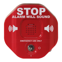
The Exit Stopper® (STI-6400 Series) is a security device designed to prevent unauthorized exits and alert personnel to door openings. It is manufactured by Safety Technology International (STI) and comes with a three-year warranty on most products, or a one-year limited warranty from the date of purchase. An electronic warranty form is available at www.sti-usa.com/wc14.

Function Description:

The Exit Stopper is primarily an alarm system that attaches to a door. When the door is opened, the device triggers an alarm, notifying staff of the event. It can be configured for immediate arming or with a 15-second delay, and for immediate tripping or with a 15-second delay. The alarm shut-off can be based on duration, with options for approximately 3 seconds after the door closes, 30 seconds, 180 seconds, or continuous alarm. It also features a 30-second annunciator mode. The device includes a low battery detection feature, which can be turned on or off. The alarm volume can be set to high or low. Additionally, it offers dry contact relay functionality, which can be configured as OFF or ON.

Important Technical Specifications:

  • Mounting: The device requires drilling for installation. For the base, four holes 1" (25mm) deep are needed, drilled with a 3/16" (4.5mm) bit for plastic anchors, or a 9/64" (3.5mm) bit for wood or steel. It is mounted using four M4 x 25mm screws. The reed magnet requires drilling with a 3/16" (4.5mm) bit for plastic anchors, or a 1/8" (3mm) bit for wood or steel, and is mounted with two M3.5 x 32mm screws.
  • Power: The device is battery-powered. The battery needs to be unwrapped and connected during setup.
  • Controls: The device features a key switch for arming/disarming and a DIP switch for configuring various settings.
  • Indicators: An LED indicator is present, which should not be touched.

Usage Features:

  • Setup:
    1. Ensure the key is in the OFF position.
    2. Remove the security screw using the provided wrench.
    3. Remove the cover from the base by pushing on the lock to separate it.
    4. Configure settings using the DIP switches. The manual provides a detailed switch table for various options, including arming delay, trip delay, alarm duration, annunciator mode, low battery detection, volume, and dry contact relay function. Default settings are indicated in the switch table.
    5. Unwrap and connect the battery.
    6. The device includes a terminal block for remote and relay options; refer to the full online installation guide for wiring connections.
    7. Test the device by placing a magnet next to the reed, turning the key to ON, and then separating the magnet from the reed.
    8. Apply the desired language label.
  • Mounting:
    1. Place the reed magnet at the desired location (top, right, bottom, or left) on the door frame.
    2. Position the base on the door, mark and drill four holes as per specifications, and mount it using the provided screws.
    3. Install the reed magnet by marking, drilling, and mounting it with the specified screws.
    4. Test the device by turning the key to ON and opening the door to ensure the alarm sounds.
    5. Replace the cover, snapping the lid from the top, and secure it with the security screw.
  • Configuration Options (via DIP Switches):
    • Arming: Immediate (OFF*) or 15-second delay (ON).
    • Trip: Immediate (OFF*) or 15-second delay (ON).
    • Shut-off based on duration (switches 4 & 5):
      • Shut-off approx. 3 sec. after door closes (OFF* OFF*).
      • 30-second alarm (OFF ON).
      • 180-second alarm (ON OFF).
      • Continuous alarm (ON ON).
    • 30-second annunciator mode: ON OFF.
    • Low battery detection: Turn switch off (OFF*) or Turn switch on (ON).
    • Volume: High (ON*) or Low (OFF).
    • Dry contact relay function: OFF (OFF*) or ON (ON).
    • Note: Disconnect all power sources before changing switch settings.

Maintenance Features:

  • Battery Replacement: The battery is user-accessible for replacement.
  • Security Screw: The device is secured with a security screw, which helps prevent tampering.
  • Warranty: The product comes with a warranty, ensuring support for potential defects.

Important Warnings:

  • This product can expose users to chemicals including Dichloromethane, which is known to the State of California to cause cancer, and Bisphenol A (BPA), which is known to the State of California to cause birth defects or other reproductive harm. For more information, refer to www.P65Warnings.ca.gov.
  • The LED indicator should not be touched.

The Exit Stopper is designed to be a reliable and configurable security solution for doors, providing alerts and deterring unauthorized exits.

Exit Stopper STI-6400 Series Specifications

General IconGeneral
BrandExit Stopper
ModelSTI-6400 Series
CategorySecurity System
LanguageEnglish