7.Readthereadingonthedisplay.ForDCcurrentmeasurements,thepolarityofthepositive(+)outputleadoftheclampwill
be indicated as well.
Note:
1. ln manual range mode, when the display shows the overrange indicator "OL", a higher range should to be selected.
2. Don’t touch the circuit under test with hand or skin.
3. Matching problem about the meter and the sensitivity of the clamp:
a. The sensitivity of the matching damp is 0.1A/0.1mV. lf you use a matching clamp, the present indicated value is same
to the measured value.
b. If you use a clamp whose sensitivity does not equal 0.1A/0.1 mV, you should multiply the present reading by a factor
which is determined by the used clamp, the result is the measured value.
To determine the factor, please refer to the instruction of the clamp which you use.
Measuring Resistance
1.Connecttheblacktestleadtothe"COM"jackandtheredtestleadtothe"INPUTʺjack.
2. Set the range switch to
Ω range.
3.SelectautorangeormanualrangemodewilhtheʺRANGEʺbutton.
4.Connectthetestleadsacrosstheloadtobemeasured.Readthereadingonthedisplay.
Note:
1.Forresistancemeasurements>1MΩ,themetermaytakeafewsecondstostabilizereading.Thisisnormalforhigh-
resistance measurements.
2. When the input is not connected, i.e. at open circuit, the symbol "OL" will be displayed as an overrange indicator.
3. Before measuring in-circuit resistance, be sure that the circuit under test has all power removed and all capacitors have
been fully discharged.
4.lnmanualrangemode,whenthedisplayshowstheoverrangeindicator"OLʺ,ahigherrangehastobeselected.
Measuring Capacitance
1.Connecttheblacktestleadtothe"COMʺjackandtheredtestleadtolhe"INPUTʺjack.
2. Set the range switch to desired "1000µF","20µFʺ or "nFʺ position.
3.Selectautorangeormanualrangemodewilhthe"RANGEʺbutton.
4. Connect test leads across the capacitor to be measured. Make sure that the polarity of the capacitor is observed.
(The red test lead should be connected to the anode of the capacitor, and the black one should be connected to the
cathode of the capacitor.)
5.Readthereadingonthedisplay.
Note:
ln small range, before the test leads are connected to the capacitor, the display may show a reading. This is normal because
of the stray capacitance of the test leads and input circuit of the meter and will not affect the measurement accuracy.
Continuity Test
1.Connecttheblacktestleadtothe"COMʺjackandtheredtestleadtothe"INPUTʺjack.
2. Set the range switch to
range.
3. Press the "FUNC." buttonuntilthesymbolʺ
ʺappearsonthedisplay.
4. Connect the test leads across the circuit to be measured.
5.Iftheresistanceislowerthanabout30Ω,thebuilt-inbuzzerwillsound.
Note:
Before test, disconnect all power to the circuit to be tested and discharged all capacitors fully.
Diode Test
1. Connect the black test lead to the "COM" jack and the red test lead to the "INPUT" jack (Note: The polarity of the red test
leadispositive"+ʺ).
2. Set the range switch to
range.
3. Press the "FUNC.ʺbuttonuntilthesymbolʺ ʺappearsonthedisplay.
4. Connect the red test lead to the anode of the diode to be tested and the black test lead to the cathode of the diode.
5. The display will show the approximate forward voltage drop of the diode. If the connections are reversed, "OL" will be
shown on the display.
Transistor Test
1. Set the range switch to
hFE position.
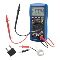
2.RefertotheFigure2,connecttheadaptertothe"COM"jackandthe"INPUT"jack.Don’treversetheconnection.
3. ldentify whether the transistor is NPN or PNP type and locale emitter, base and collector leads. lnsert the leads of the
transistor to be tested into the proper holes of the transistor test socket of the adapter.
4. The display will show the approximate
hFE value.