Do you have a question about the Expolite TourLED Pro 28 Zoom and is the answer not in the manual?
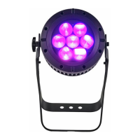
Provides key technical specifications including model, voltage, dimensions, and IP rating.
Outlines important safety precautions for installation, operation, and maintenance of the product.
Details methods for hanging and upright mounting of the fixture, including safety cable usage.
Specifies power connection configurations for 220V and 110V systems and signal cable limitations.
Explains how to enter password, adjust white color temperature, and calibrate RGB parameters.
Details how to set the small position for the zoom function to limit fixture control via DMX.
Allows adjustment of key operational settings like lock-out, uploads, and calibration.
Selects the DMX mode, such as TOUR, TR16, ARC.1, AR1.D, ARC.2, AR2.D, AR2.S, HSV, AR2.Z, FULL.
Edits custom programs (PR.01 to PR.10) with up to 30 steps each, using various parameters.
Combines Red, Green, Blue, White, and Zoom to create an infinite range of colors (0-255).
Selects and activates pre-programmed auto (AT.01-AT.10) or custom (PR.01-PR.10) programs.
Sets the fixture's working mode to DMX for controller operation or SLAVE for Master-Slave setup.
Sets the DMX address for fixture control, ranging from 001 to 512.
Details the DMX channel assignments and their corresponding functions for fixture control.
Details maintenance procedures and component identification for the fixture, including an exploded view.
| Zoom | Yes |
|---|---|
| CRI | >80 |
| Frequency | 50/60 Hz |
| Power | 280W |
| Input Voltage | 100-240V |
| Lifespan | 50000 hours |