ENGLISH
MOUNTING THE ROADSIDE PANEL
MOUNTING THE HANDSET
GENERAL INFORMATION
This 4 wire door phone enables controlling a strike or automatic
gate opener* (*in this case plan to order the WE 8111 Bis option)
KIT COMPONENTS
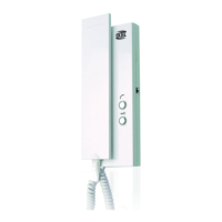
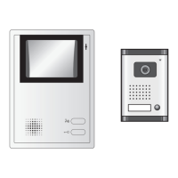
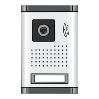
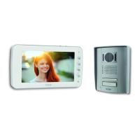
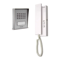
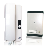
An internal handset•A roadside panel•A bag of screws
•Release the 2 screw caps (A) with a small flat screwdriver
•Remove the 2 attachment screws (B) • Feed the wires from the
handset through the hole (C) • Fix the rear frame with 2 screws (E)
on the pillar at a height of approximately 1.60 m. Important : Put
a gasket on the upper half between the support of the roadside
panel and the wall (D). •Access to the nameplate by the rear of
the panel. Remove the nameplate applying a light pressure on the
sides of the call button support. After having written the name, put
back the call button in its original position. • Connect the wires of
the roadside panel as indicated on the wiring diagram • Put back
the front panel of the roadside panel with the 2 screws (B)•Replace
the 2 screw caps taking care of putting the one with an hole (G) at
the bottom.
• Fix the attachment screws on the wall, respect the 16.5 cm
centre distance between the 2 attachment screws. Note the
handset must be placed at approximately 1.60 m from the ground.
•Connect the wire 1 of the roadside panel to the terminal 1 of the
handset•Connect the wire 2 of the roadside panel to the terminal
2 of the handset•Connect the terminals 8 and 9 directly to the
strike or electric lock.*•Mount the handset to the wall•Plug the
supply cord into a 230 VAC outlet.
*If you order an automatic gate opener, plan to order the we8111 option.





 To Next Page