13
Te gebruiken draden : • 4+2 draden 6 /10e tot 25 m
• 4+2 draden 1.5
mm
2
van 25 tot 100 m
1. De draden goed aansluiten volgens het draadschema hieronder.
2. Om de camera aan te sluiten zijn slechts 4 draden nodig voor alle functies.
•
Klem “1” van het scherm op klem “1” van de camera
•
Klem “2” van het scherm op klem “2” van de camera
•
Klem “3” van het scherm op klem “3” van de camera
•
Klem “4” van het scherm op klem “4” van de camera
op G e l e t : d e d r a d e n in G e e n G e v a l v e r d u b b e l e n o M d e d o o r s n e d e t e v e r G r o t e n .
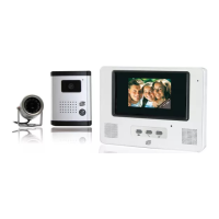
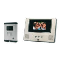
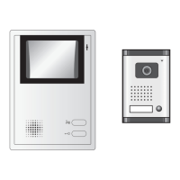
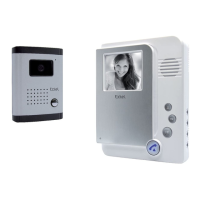
a. Aansluiting van de videofoon
Zu verwendende Drähte: • Bis 25 m Verdrahtungslänge: 4x Drähte 6/10 mm +2
• Bis 100 m Verdrahtungslänge: 4x Drähte 1.5
mm
2
+2
1. Die Drähte entsprechend dem Verdrahtungsplan anschließen.
2. Für den Anschluss der Kamera sind nur 4 Drähte für sämtliche Funktionen erforderlich.
•Klemme “1” des Displays auf der Klemme “1” der Kamera.
•Klemme “2” des Displays auf der Klemme “2” der Kamera.
•Klemme “3” des Displays auf der Klemme “3” der Kamera.
•Klemme “4” des Displays auf der Klemme “4” der Kamera.
vo r s i c H t : die dr ä H t e d ü r f e n a u f k e i n e n fa l l (z u r er H ö H u n G d e s Qu e r s c H n i t t s ) v e r d o p p e lt w e r d e n .
a.
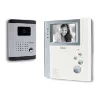
Installation der Außenstation (Außen-Kamera)
Use the following wires: • lengths up to 25 metres: 4 x 6/10 wires + 2
• lengths between 25 and 100 metres: 4 x 1.5
mm
2
wires + 2
1. Connect the wires securely following the wiring diagram below.
2. To connect the video camera, 4 wires are needed for all the functions.
•Terminal “1” on the screen to terminal “1” of the video camera.
•Terminal “2” on the screen to terminal “2” of the video camera.
•Terminal “3” on the screen to terminal “3” of the video camera.
•Terminal “4” on the screen to terminal “4” of the video camera.
c
a u t i o n
:
u n d e r
n o
c i r c u M s t a n c e s
s H o u l d
t H e
w i r e s
b e
d o u b l e d
t o
M a k e
t H e M
t H i c k e r
a.
Connecting the videophone
Cavi da utilizzare: • 4 + 2 cavi 6 /10 fino a 25 m
• 4 + 2 cavi 1.5
mm
2
da 25 a 100 m
1. Collegare correttamente i cavi rispettando lo schema di cablaggio.
2. Per collegare la telecamera, sono necessari solo 4 cavi.
a
t t e n z i o n e
:
n o n
b i s o G n a
in
n e s s u n
c a s o
r a d d o p p i a r e
i
c a v i
p e r
a u M e n t a r e
l a
s e z i o n e
.
a. Collegamento del videocitofono