EasyManua.ls Logo

Extel XB250 - User Manual

Extel XB250
2 pages
Print Icon
To Next Page IconTo Next Page
Loading...
2. EQUIPMENT REQUIRED (NOT SUPPLIED)
The tools and screws required for the installation must be in good condition and compliant with applicable safety standards.
Please use screws compatible with the bracket to which the motors will be attached (e.g. anchor studs, threaded rod with chemical seal, etc.)
1 drill
1 fl at head screwdriver 1 pencil
1 spirit level
1 x 13mm spanner
1 measuring tape
1 Phillips screwdriver
Photocells
¡[
[
[
¡[
¡
Attaching the
brackets
on the gate:
Choose a screw/nut
system compatible
with the thickness of
the gate. There are 4
attachment points
10m cable
4 x 6/10
Flashing light Motor
Attaching the motors
onto the posts
3m cable
2 x 0.5mm
2
8m cable
2 x 1.5mm
2
Thank you for purchasing an EXTEL automatic gate opener.
This document is a quick start guide detailing the main installation steps as well as the equipment required. To perform the installation, please
download the installation manual at the following address: www.avidsen.com
Warning: The safety instructions and installation instructions can be found in the installation manual. Follow all these instructions, as an as
incorrect installation can cause serious injuries.
1
Motor lock screws
2
Post mounting bracket
3
Main motor with electronic card
4
Secondary motor
5
Screws for attaching the rear arm to the
motor
6
Rear arm
7
Pin
8
Pin axis
9
Front arm
10
Gate mounting bracket
11
Photocells and screws
12
Flashing light and screws
13
Remote controls
14
Override key
15
Installation template
16
Accessories for the solar kit
17
Backup fuses
1
x 2
2
x 2
13
x 2
6
x 2
7
x 4
8
x 4
9
x 2
10
x 2
3
x 1
4
x 1
5
x 2
12
x 1
12
x 2
12
x 2
14
x 1
15
x 1
17
x 1
16
x 1
V1
EN
Ref. 761005
XB250
ELECTRIC GATE
OPENER KIT
For 2-panel swing gates
11
x 1
11
x 6
11
x 6
11
x 4
1. DESCRIPTION
Question and Answer IconNeed help?

Do you have a question about the Extel XB250 and is the answer not in the manual?

Summary

Product Components and Parts

Motor Lock Screws

Screws used for securing the motor lock mechanism.

Post Mounting Bracket

Bracket for attaching the gate opener motor to the post.

Main Motor with Electronic Card

The primary motor unit containing the main control electronics.

Secondary Motor

The secondary motor unit for the second gate panel.

Rear Arm Attachment Screws

Screws for connecting the rear arm to the motor housing.

Rear Arm

The rear arm component of the gate opener mechanism.

Pin

A pin used for securing components within the gate opener system.

Pin Axis

The axis or rod for the pin used in the gate opener assembly.

Front Arm

The front arm component that connects to the gate panel.

Gate Mounting Bracket

Bracket designed for mounting the gate opener to the gate itself.

Photocells and Screws

Safety photocells and associated screws for installation.

Flashing Light and Screws

Warning flashing light and screws for mounting.

Remote Controls

Remote controls for operating the automatic gate opener.

Override Key

Key used for manual override of the gate opener system.

Installation Template

A template to aid in the precise placement and installation of components.

Solar Kit Accessories

Various accessories intended for use with an optional solar power kit.

Backup Fuses

Spare fuses included for the protection of the gate opener electronics.

Required Tools and Materials

Essential Tools for Installation

List of necessary hand tools including screwdrivers, drill, spirit level, and spanner.

Cables and Mounting Hardware

Details on required cables for motors and photocells, and fixing systems for gate and posts.

Installation Guide and Setup

Overview and Cable Requirements

Guidance on cable types suitable for outdoor use and compliance with standards.

Installation Steps Summary

Outlines the four main stages of installation: component fitting, electrical connection, app setup, and testing.

Electrical Connection Details

Specific instructions for wiring motors, flashing lights, photocells, and mains power.

Software Setup and Operation

Instructions for using the EXTEL UMII app and manual mode for initial setup and remote pairing.

Operational Testing Procedures

Guidance on conducting tests to ensure the gate opener functions correctly and safely.

EU Declaration of Conformity

Overview

The EXTEL XB250 is an electric gate opener kit designed for two-panel swing gates, identified by reference number 761005. This document serves as a quick start guide, outlining the main installation steps and required equipment. For a complete and safe installation, users are directed to download the full installation manual from www.avidsen.com, which contains crucial safety instructions and detailed installation procedures. Failure to follow these instructions can lead to serious injuries.

Function Description:

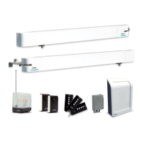
The EXTEL XB250 kit automates the opening and closing of two-panel swing gates. It comprises two motors (a main motor with an electronic card and a secondary motor), a flashing light for visual alerts, and photocells for obstacle detection, enhancing safety during operation. The system can be controlled via remote controls included in the kit or through the EXTEL UMII smartphone application, offering modern convenience and advanced configuration options.

Kit Components (Description and Quantity):

The kit includes a comprehensive set of parts necessary for installation and operation:

  • Motors and Mounting Hardware:
    • Motor lock screws (x2)
    • Post mounting bracket (x1)
    • Main motor with electronic card (x1)
    • Secondary motor (x1)
    • Screws for attaching the rear arm to the motor (x2)
    • Rear arm (x2)
    • Pin (x4)
    • Pin axis (x4)
    • Front arm (x2)
    • Gate mounting bracket (x2)
  • Safety and Signaling:
    • Photocells and screws (x1 set, comprising 6 photocells and 4 screws)
    • Flashing light and screws (x1 set, comprising 1 flashing light and 2 screws)
  • Control and Accessories:
    • Remote controls (x2)
    • Override key (x1)
    • Installation template (x1)
    • Accessories for the solar kit (x1) - Note: Solar kit components are separate accessories, not included in the base kit.
    • Backup fuses (x1)

Required Equipment (Not Supplied):

To ensure a successful and safe installation, specific tools and materials are required, which are not included in the kit:

  • Basic Hand Tools:
    • 1 flat head screwdriver
    • 1 Phillips screwdriver
    • 1 x 13mm spanner
    • 1 drill
    • 1 spirit level
    • 1 measuring tape
    • 1 pencil
  • Mounting Hardware:
    • Screws compatible with the bracket and post material (e.g., anchor studs, threaded rod with chemical seal). The manual emphasizes using screws suitable for the specific gate and post materials.
  • Cabling (Specific to each component):
    • Flashing Light: 3m cable, 2 x 0.5mm²
    • Motor: 8m cable, 2 x 1.5mm²
    • Photocells: 10m cable, 4 x 6/10
    • Attaching brackets on the gate: Screw/nut system compatible with gate thickness (4 attachment points).
    • Attaching motors onto the posts: 6 screws (Ø12x100) and 6 screws (Ø8x100).

Important Technical Specifications (Cabling):

The installation requires specific types and lengths of cables, which must be appropriate for outdoor use (e.g., H07RN-F) and comply with NFC 15-100 standards for cable runs between posts.

  • 230VAC Power Line:
    • Cable 3 x 2.5mm² (for lengths > 30m)
    • Cable 3 x 1.5mm² (for lengths < 30m)
    • Max length: Unlimited
  • Flashing Light: Cable 2 x 0.5mm², Max length: 15m
  • Secondary Motor: 2 x 1.5mm² cable, Max length: 10m
  • Reception Photocells (RX): 4 x 6/10 cable, Max length: 10m
  • Transmission Photocells (TX): 4 x 6/10 cable, Max length: 10m The power cable for the opposite geared motor must be buried 80cm deep with a red warning mesh for safety.

Usage Features:

The EXTEL XB250 offers flexible control and configuration options:

  • Remote Control: The kit includes two remote controls for direct operation of the gate. Pairing is achieved by pressing the button on the remote control and then the specific button on the electronic card.
  • Smartphone Application (EXTEL UMII): Users can download the EXTEL UMII app to their smartphone for a faster setup and advanced settings configuration. After registering and adding the motor (indicated by a flashing blue light), the app guides the user through the setup process.
  • Manual Mode (Electronic Card):
    • Auto-learning Process: Initiated by pressing a button on the electronic card 3 times. An orange light flashes during the motor sweep learning process.
    • Adding Remote Controls: Pressing a button once on the electronic card makes a green light flash, indicating readiness for remote control pairing.
    • Reset: Holding a button for 8 seconds initiates a reset, confirmed by 5 purple flashes. The light then turns blue, indicating readiness to add the motor to the app.

Installation Process (4-Step Overview):

  1. Physical Installation: Mount the motors, flashing light, and photocells. The main motor is fixed to the post with the power supply.
  2. Electrical Connection: Connect the secondary motor, flashing light, and photocells to the electronic card in the main motor. The transformer must be connected to the mains by qualified personnel (electrician). Optional products like a videophone, keypad, or backup battery can also be connected.
  3. Getting Started: Configure the system either through the EXTEL UMII application or manually via the electronic card.
  4. Operational Testing: Conduct thorough operational tests (open/close, obstacle detection, photocell beam cut) to ensure proper functioning and familiarize with the automatism. Adjust settings like motor power if necessary.

Maintenance Features:

While not explicitly detailed as "maintenance features" in the quick start guide, the inclusion of backup fuses (x1) suggests a basic level of user-replaceable components for minor electrical issues. The emphasis on downloading the full manual implies that detailed maintenance procedures and troubleshooting guides would be found there. The requirement for qualified personnel for mains connection also highlights the importance of professional intervention for certain electrical aspects, which can be considered a form of specialized maintenance.

EU Declaration of Conformity:

Avidsen declares that the EXTEL XB250 complies with the essential requirements of several EU directives:

  • RED Directive 2014/53/EU: For radio equipment.
  • Directive 2014/35/EU: For user health and safety.
  • Directive 2014/30/EU: For electromagnetic compatibility.
  • Directive 2014/53/EU: For efficient use of the radio spectrum. The full declaration of compliance is available on www.avidsen.com. Signed by Alexandre Chaverot, CEO, in Tours on 12/06/2023.

Extel XB250 Specifications

General IconGeneral
BrandExtel
ModelXB250
CategoryGate Opener
LanguageEnglish

Related product manuals