5
(546 mm)
21.875"
(556 mm)
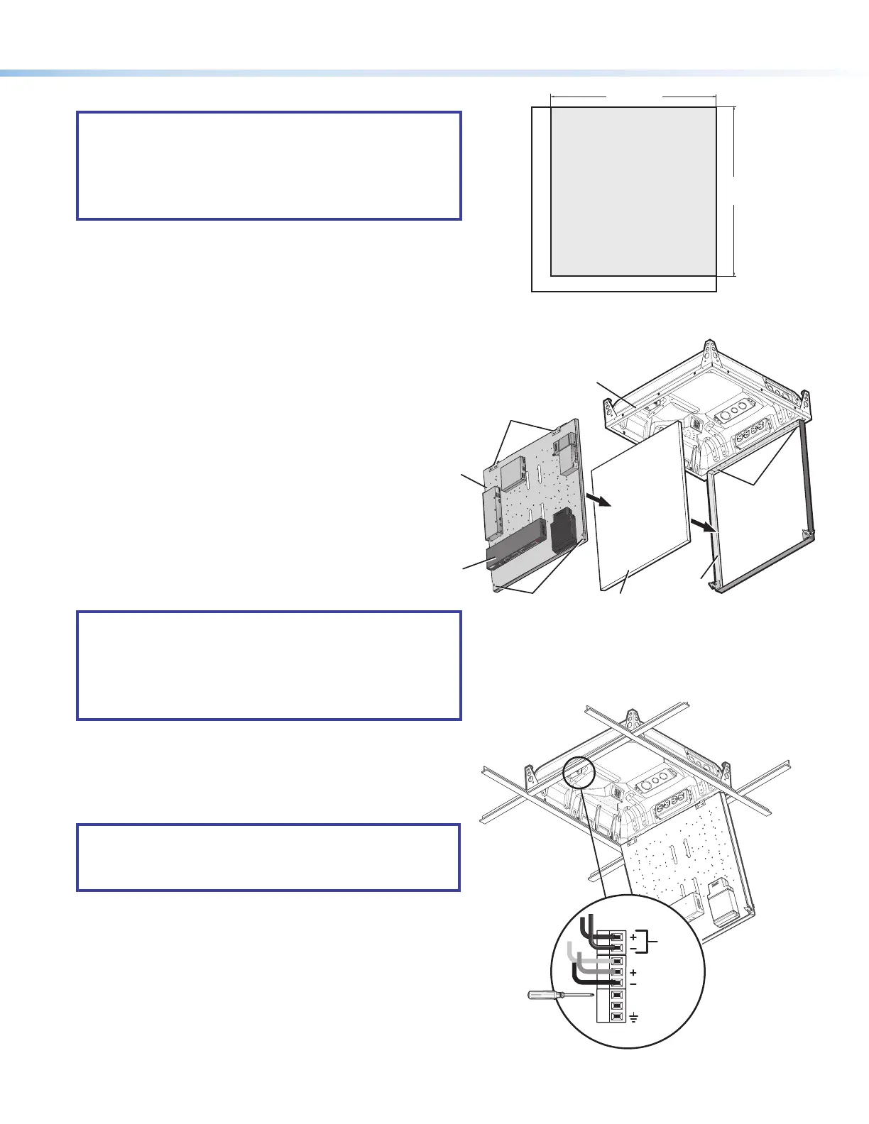
Cut the ceiling tile to
21.5 x 21.875 inches
and use that part for
insertion into the
access door
.
Example: 24 x 24 inch Ceiling Tile
Bottom of Door (Door Locks)
Step 7 — Cut and install the ceiling tile in the access door.
NOTES:
• The door can accept a ceiling tile thicknesses of ½ inch
to 1¼ inches. Check the tile thickness before cutting.
• If the ceiling tiles have a specic pattern direction, ensure
the overall pattern direction is maintained when cutting
and tting the cut tile insert into the access door.
a. Mark the dimensions (21.5 inches by 21.875 inches) for the
PVM 220 access door on the ceiling tile and cut the tile to size.
b. With the access door open, insert the cut ceiling tile into the
door frame (see gure 11, below right).
Step 8 — Install the device mounting plate onto the access
door.
To fit the mounting plate and devices on the access door:
a. Align and slide the device mounting plate onto the two
hinge pins located at the top of the door frame.
b. Secure the plate into place with the two mounting
plate screws, located at the bottom of the
door frame.
Step 9 — Connect the cables to the devices.
NOTES:
• See the PoleVault System Installation Guide or the
relevant PoleVault switcher user guide for connecting
cables and devices to the PVS device.
• For cable connections to optional devices see the
relevant device guide or manual.
Connect and dress the device cables as needed, providing
enough slack to open and close the access door.
If equipped with a fan, plug the fan controller cable into the switcher
power supply. The fan comes pre-wired to the controller in the
enclosure.
NOTE: The fan is controlled automatically by the internal
temperature of the PVM 220. The fan can also be turned on
or off manually (see below for wiring). Manually controlling
the fan overrides the automatic thermal control mode.
The fan can be wired to a control system for manual On/Off as
follows (see gure 12 for connectors):
• For manual On, wire a latching relay to the On and Ground
connectors on the fan controller.
• For manual Off, wire a latching relay to the Off and Ground
connectors on the fan controller.
Step 10 — Verify and configure the setup.
Turn on the power to all the devices. Verify and congure the
system (see the relevant PoleVault switcher user guide available
at www.extron.com for full details).
Figure 10. Cut the ceiling tile for insertion into the
access door.
Figure 11. Insert the ceiling tile and attach the device
mounting plate to the door frame.
P
V
S
40
5
S
A
I
P
PO
L
E
V
A
ULT
SW
I
TCHER
I
NPU
T
S
AUD
I
O
L
E
VEL
ADJUS
T
PAG
I
NG
S
E
NS
O
R
S
E
NSI
T
I
V
I
T
Y
P
E
AK
NO
R
M
A
L
S
I
G
N
A
L
V
O
I
C
ELIF
T
P
E
AK
NO
R
M
A
L
S
I
G
N
A
L
I
N
P
UT
SELECT
C
O
NFI
G
R
1
2
3
4
5
A
U
X
AU
D
IO
E
12 V
TACH (Yellow)
FAN (Red)
FAN (Black)
ON
OFF
GROUND
Figure 12. If equipped with a fan, wire the fan controller
for an manual On/Off option.
P
VS
4
0
5
S
A
IP
P
O
LEVA
U
LT
S
W
I
TC
H
E
R
I
NPUT
S
A
U
D
I
O
L
EVE
L
A
D
JU
S
T
P
AG
I
N
G
S
E
NS
O
R
S
E
N
S
I
T
I
V
IT
Y
PE
A
K
NO
R
M
A
L
S
IG
N
AL
V
OI
CELI
F
T
PE
A
K
NO
R
M
A
L
S
IGN
A
L
I
N
P
UT
SE
L
EC
T
CO
NF
I
G
R
1
2
3
4
5
A
U
X
A
U
D
I
O
E
Ceiling Tile
Insert
Door Frame
Device Mounting
Plate (with devices
installed)
PVM 220 Enclosure
PoleVault
Switcher
(front panel
facing down)
Device Mounting
Plate Screws
Device Mounting
Plate Hinge Pins
Device Mounting
Plate Hinges
 Loading...