3
Product Category
Front Panel Features
AABBCCAA
D
D
E
E EE
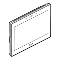
Figure 3. TLP Pro 725M Front Panel
A
Motion sensor — Detects motion between three to ve feet from the touchpanel, and at least 15° from the center axis.
• When no motion has been detected for a user-dened period of time, the touchpanel enters sleep mode.
• When motion is detected by the sensor, the screen display is restored and active.
B
Communication LED — Shows the conguration and connection status of the touchpanel:
• Unlit during normal operation (the touchpanel is congured and connected to an IP Link Pro control processor).
• Blinks red if the touchpanel has been congured but is not connected to an IP Link Pro control processor.
• Lit solidly red if the touchpanel has not been congured.
The indicator can be toggled between enabled and disabled, using the Setup Menu (see the next page).
C
Light sensor — Monitors ambient light level and adjusts screen brightness.
D
Capacitive touchscreen — A 7-inch screen with 1024x600 resolution.
E
Status lights — Two LED light bars, one on either side of the screen, which can be programmed to provide system feedback.
• Light red or green • Blink or light continuously
For information about programming these LEDs, see the Global Configurator Help File and Global Scripter Help File.
Rear Panel Features
CCAABB
EE
F
F
G
G
HH
DD
DD
DD
D
D
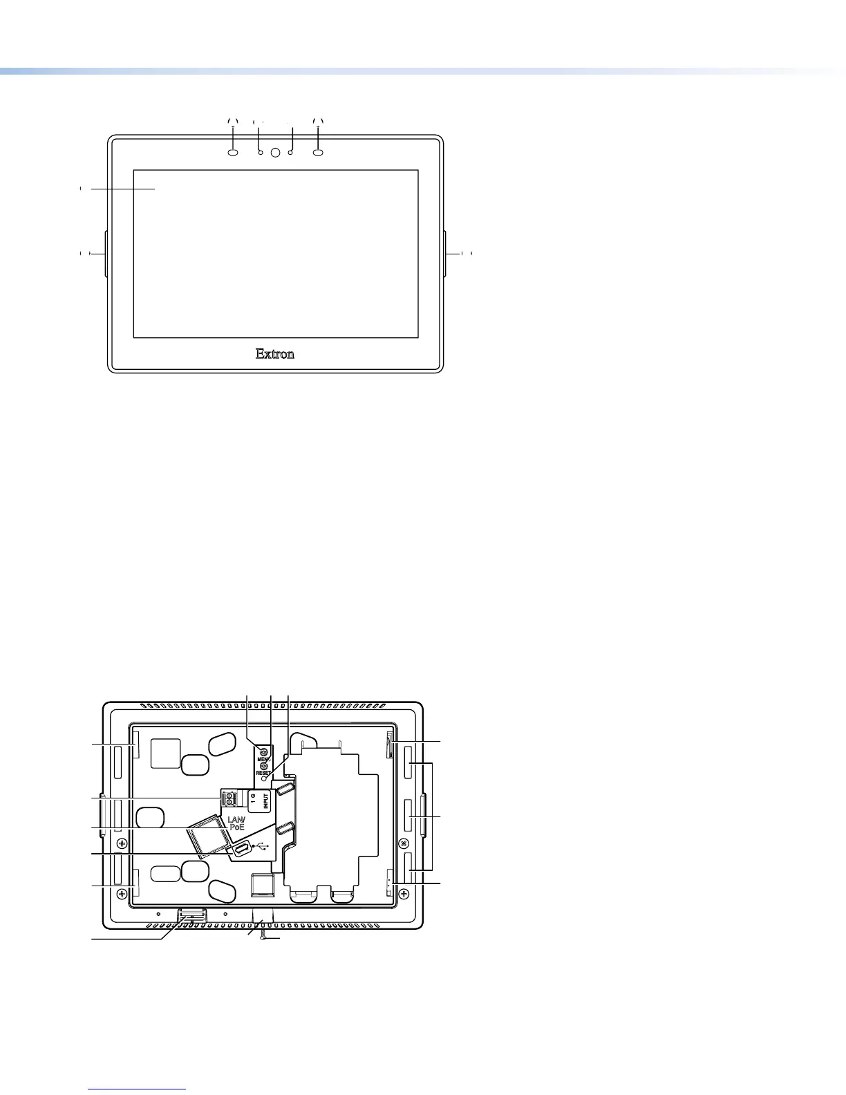
Figure 4. TLP Pro 725M Rear Panel
A
Menu Button— Activates the setup menu (see Setup Menu on the next page).
B
Reset Button— Pressing the Reset button allows the unit to be reset in any of three different modes (for an overview, see
Reset Modes, on the next page).
C
Reset LED— Provides feedback about the reset status when the user presses the Reset button (see Reset Modes).
gure 4
Menu Button
Reset Button
Reset LED
A
Menu Button
B
Reset Button
C
Reset LED
D
Mounting Slots (4)
E
Digital Input Monitoring Port
F
LAN/PoE Connector
G
USB Port
H
Rear Panel Status Lights (6)
I
Speaker
J
Slot for Mounting Plate
K
Mounting Screw
 Loading...