-
-
BUSBUS BUSBUS
1
BUSBU
DS1
ON
1 2 3 4
BUSBUS
DS1
ON
1 2 3 4
DS1
ON
1 2 3 4
DS1
L
1
D
1
D
DL
DL
BU
“ XIB ” BU
INTERFA
E
I
n
v
s
o
nn
t
t
J
L
J
P
term
na
o
t
XIB”
t
unuse
term
na
mus
connecte
th
negativ
o
th
FAA
contro
oar
t
BU
p
otoce
connecte
t
XIB”
con
igur
D
t
igur
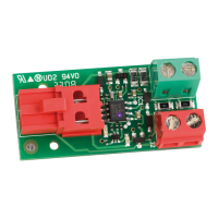
J1
( RED )
Connector to be connected to
the “2easy” BUS coupling
on FAAC control board
J2
( RED )
Terminal board for the connection
of BUS accessories
(2easy photocells, encoder etc..)
J3 CL
( GREEN )
Terminal for the connection of
devices
operating at closure (CL) ,
with N.C. contact
(E.G. PHOTOCELLS, EDGES, ETC...)
J3 OP
( GREEN )
Terminal for the connection of
devices operating at opening (OP)
with N.C. contact
(E.G. PHOTOCELLS, EDGES, ETC...)
DL1
LED for diagnostics of devices
connected to the J3 OP terminal
(see diagnostic table)
DL2
LED for diagnostics of devices
connected to the J3 CL terminal
(see diagnostic table)
DIAGNOSTICS
OFF SLOW FLASHING
(FLASH EVERY 5 secs.)
ON STEADY BEAM FAST FLASHING
(FLASH EVERY 0.5 secs)
ALTERNATE FLASHING OF
“DL1” AND “DL2” LEDs
DL1
“XIB” board
broken
or not
powered
J3 OP terminal
open.
E.G. PHOTOCELL
ENGAGED,
NOT ALIGNED OR
NOT CONNECTED (*)
J3 OP terminal
closed
E.G. PHOTOCELL
NOT ENGAGED
AND ALIGNED
BUS photocell, connected to the
J2 terminal of the “XIB”, with the
configuration of:
DS1: OFF;ON;ON;ON
USE ANOTHER
DS1 COMBINATION
The “XIB” BUS interface
is not connected to a
“2easy” bus
output on the
FAAC control board
CONNECT
THE “XIB” INTERFACE
TO THE “2easy” BUS
TERMINAL ON THE FAAC
control board
DL2
“XIB” board
broken
or
not
powered
J3 CL terminal
open.
E.G. PHOTOCELL
ENGAGED,
NOT ALIGNED OR
NOT CONNECTED (*)
J3 CL terminal
closed
E.G. PHOTOCELL
NOT ENGAGED
AND ALIGNED
BUS photocell, connected to the
J2 terminal of the “XIB”, with the
configuration of:
DS1: ON,ON,ON,OFF
USE ANOTHER
DS1 COMBINATION
DEVI
E
N.
NTA
THE
DEVI
E
N.
NTA
BU
UPLIN
N
AA
contro
oar
BU
PH
T
ELL
easy
D
PH
T
ELL
L
UR
PH
T
ELL
PENIN
 Loading...