Do you have a question about the FABER S.p.A. GALILEO SMART BK GLASS A830 and is the answer not in the manual?
| Brand | FABER S.p.A. |
|---|---|
| Model | GALILEO SMART BK GLASS A830 |
| Category | Ventilation Hood |
| Language | English |
Read safety information in the User Manual before proceeding with installation.
Read safety information in the user manual before installation.
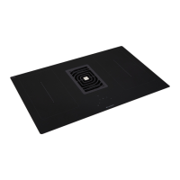
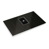
Diagrams identifying key product components.
Detailed dimensions and cut-out measurements for installation.
Visual guidance on correct and incorrect cabinet configurations for installation.
Specifies minimum clearance dimensions required around the installed unit.
Illustrates safety warnings, user restrictions, and the need for protective gloves.
Diagrams illustrating airflow paths for ventilation during operation.
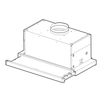
Details components and assembly for a ventilation system with H60 height.
Details components and assembly for a ventilation system with H100 height.
Specifies cabinet widths (600mm, 700mm) and required clearances (60mm, 100mm).
Details required cabinet depth (860mm/900mm) and installation height (300mm).
Provides dimensions for the cut-out in the cabinet to fit the unit.
Specifies dimensions for the countertop opening in diagram A.
Specifies dimensions for the countertop opening in diagram B.
Illustrates fitting a 30mm component and ducting in step 1x.
Explains duct length calculation (L=H-310mm) for step 2x.
Illustrates fitting a 130mm component and ducting in step 1y.
Explains duct length calculation (L=H-310mm) for step 2y.
Illustrates fitting a 230mm component and ducting in step 1z.
Explains duct length calculation (L=H-310mm) for step 2z.
Illustrates attaching components and a strap in step 3.
Depicts the process of securing component A to the unit in step 4.
Shows placing the unit and connecting the ductwork in step 5.
References ventilation configurations, directing to page 17 for details.
Illustrates the connection of ductwork for exhaust ventilation in step 6.
Details dimensions for various ducting and connector components.
Provides specifications for elbow and flexible ducting accessories.
Illustrates the assembly of ventilation components for H60 configuration.
Illustrates the assembly of ventilation components for H100 configuration.
Details the process of connecting the electrical control module and wiring.
Diagram and wiring guide for mono-phase electrical connection.
Diagram and wiring guide for bi-phase electrical connection.
Diagram and wiring guide for three-phase electrical connection.
Table mapping wire colors to connection terminals for different phases.
Illustrates inserting components, applying water, and performing checks.
Highlights electrical safety precautions when connecting to water supply.