Fig. 3
25
EN
For possible “Spare parts” orders do NOT consider the numbering in this booklet,
please refer to the “Spare parts” exploded view drawing only (from page 45).
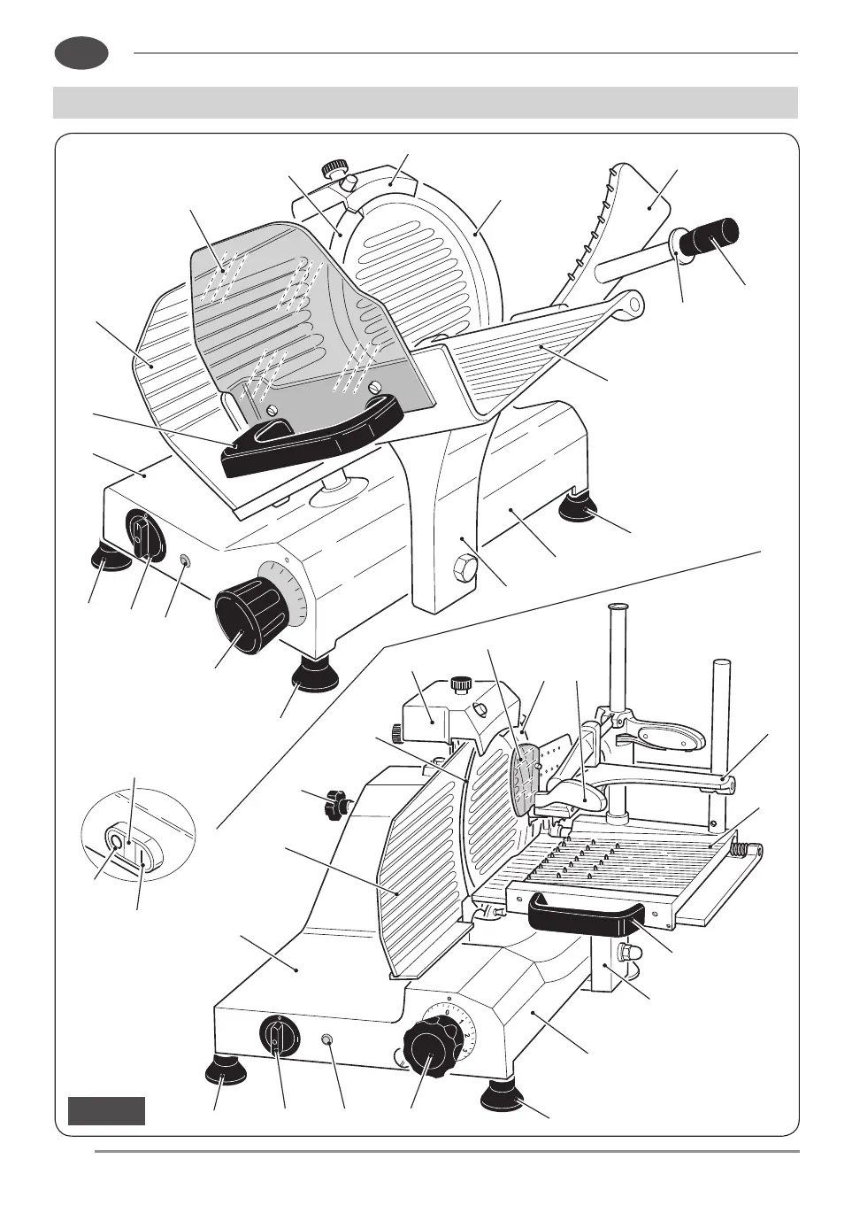
1. Base
2. Adjustable feet
3a. Startup button “I”
3b. Switch “0/I”
4. “STOP” “0” button
5. Machine running warning light
6. Slice thickness control knob
7. Carriage tray support
8. Sliding product tray
9. Blade plate
10. Product grip
11. Blade
12. Product grip handle
13. Product grip handguard
14. Tray handguard protection
15. Product tray handle
16. Blade plate tie-rod
17. Gauge plate
18. Sharpener
19. Collector surface
20. Slice guard
21. Supply cord
22. Nameplate
Fig. 4
16
20
22
21
19
1
2
4
4
5
3a
3a
6
15
8
12
17
18
11